Leaded Solder vs. The Crazy 77
Tags: computer fujitsu fm7 fm77 fm77av2 repair homemade-hardware homemade-software custom-chip-failure failure
Things don’t always go to plan! When battling one of the most complex 8-bit home computers ever made, you can expect to run into some problems.
History
The Fujitsu FM-77 is the “second” series of FM-7 machines, which you could say makes it the grandson of the FM-8 (or a weird niece of the FM-11.) Like with the transition from the NEC PC-8001 to the PC-8801, Fujitsu moved from an all-in-one wedge computer design to a separate case-and-keyboard desktop computer design.
The same general design persists, with two 6809 CPUs, but Fujitsu has taken the opportunity to add a bunch of nice performance features like improved DMA, faster graphics display (thanks to sub-CPU cycle stealing,) and much more memory.
This particular unit is the FM-77AV2, which came a little bit later and offered much improved video quality. Most notably, it offers a 320x200 mode with 4096 simultaneous colours, with no palettes, which is pretty crazy for 1985.
Fujitsu kept the FM-77 line going for awhile after this, adding even more colours and even faster internal performance, but those machines cost an absolute fortune, so we’ll not be seeing them in the immediate future.
Background
Blog friend Sampson sent me this beleagured Fujitsu. He had done a bunch of testing and inspection on the machine already.
He reported that at least two things were wrong:
- The analogue RGB video, sent from the JP21 port, did not work;
- The computer itself didn’t work, either.
After several months of fighting with it, he was preparing to send it to recycling. Graciously, he instead decided to ship one of the densest imaginable personal computers to me to see if I could fix it.
First impressions
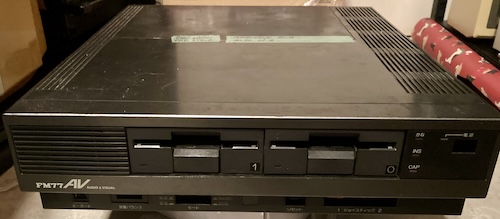
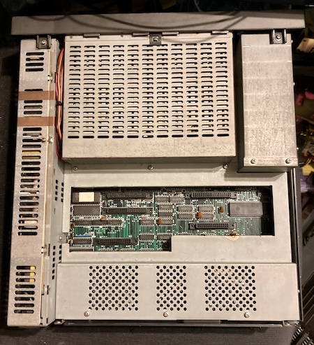
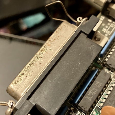
Like I said up above, this computer is friggin’ heavy. You don’t expect it, either, as the machine is not particularly large and has a plastic exterior. The most likely cause of this weight is the excessive amount of metal shielding:
The poor machine has been beaten around, with a lot of tabs broken off all the plastics, and a bunch of grease and dirt clinging to the interior.
As soon as I opened the computer, I found some ugly organic-looking gunk on the top of the shields. My first guess was that a lithium clock battery had exploded, which meant that the faults were likely to be corrosion.
Inside the card cage, I found two cards of unknown purpose.
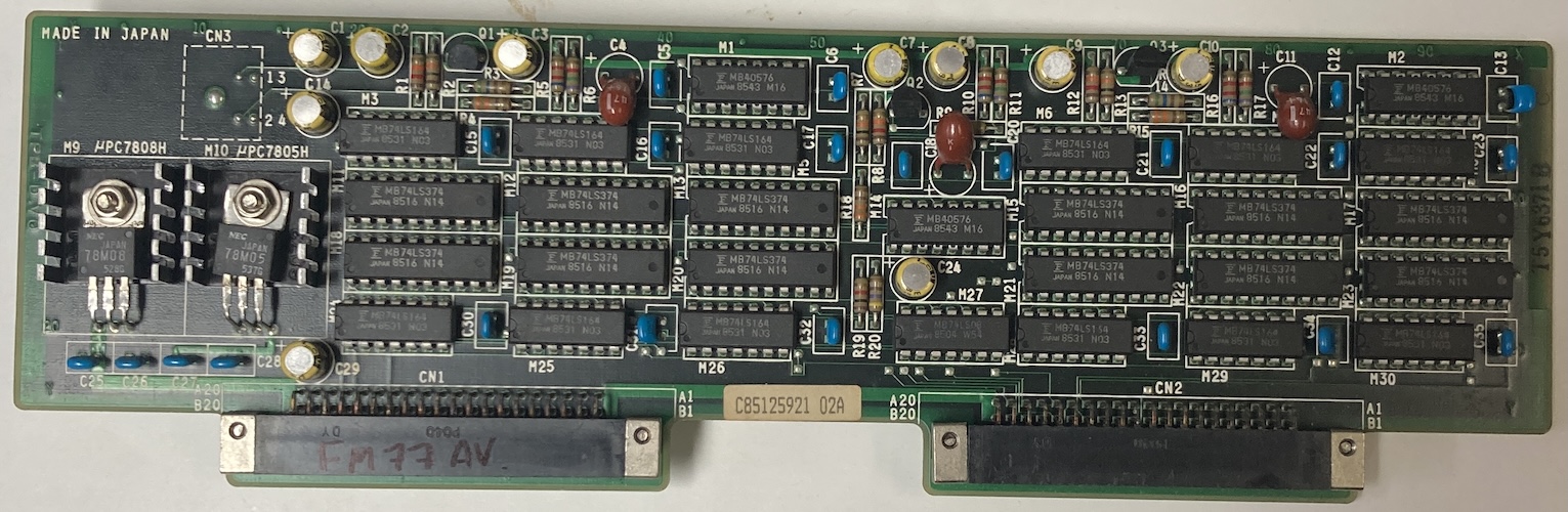
The first card has a bunch of stuff on it, plus a mini-DIN-4 connector that goes to a rotting cable with a DIN end on it.
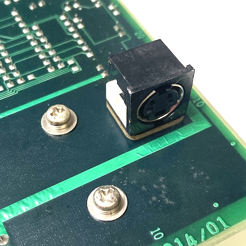
I’m not sure what it is; a search of the apparent part number (Fuijtsu D330-0001-T014/01) did not turn anything up. Maybe you know. My best guess is that this was for a hand scanner because of all the latches and counters. At the extreme end, it could possibly be a mouse, but it seems like a lot of logic for the latter.
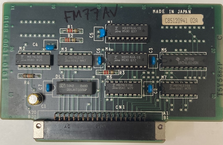
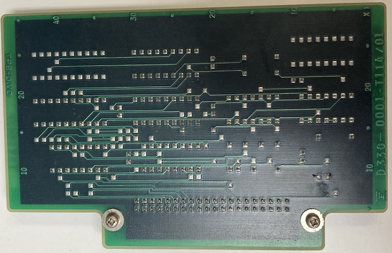
The other card is also a bit of a mystery; it’s much smaller, and it has a delay line on it as well as a small amount of MB81464 RAM. That card part number (Fujitsu D198-0001-0101, and D330-0001-T114/01) also didn’t turn up anything. Those numbers are very close to each other, which makes me wonder if these are meant to be companions. Fujitsu does tend to make “two card” solutions because they keep making their expansion bays too small.
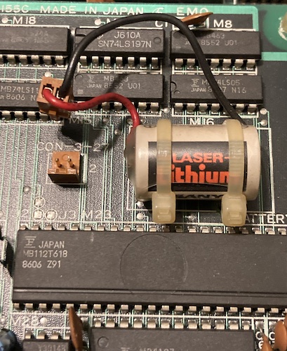
I checked their tantalum bypass caps for shorts, and found none. I noticed that a third sub-board underneath the shield had a zip-tied Sanyo “Laser Lithium” battery on it, which had not appeared to leak and was unplugged. Although I’ve never seen one of these leak, mostly because of their excessive potting, I cut the zip-ties and disposed of the battery just to be on the safe side.
Beneath the cards were more chunks of black stuff all over the interior, which is also consistent with a lithium battery failure (they like to explode and throw these all over the place.) But I couldn’t see any other lithium batteries in the area!
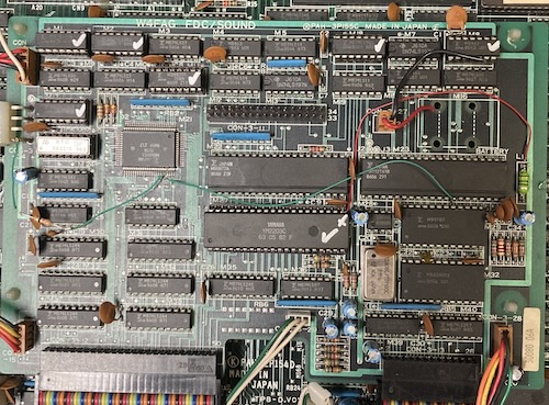
The floppy/sound board seemed to take a decent whack of the gunk, but it didn’t appear to get directly onto any parts. Or so I thought.
Like a lot of other Japanese machines, many of the metal surfaces, including the port shields, were covered in white powder that I thought might be leftover rework flux or even humidity damage. This goes for the card connectors as well.
One port had a bit of green gunk, which I couldn’t immediately identify. Maybe it is what the white gunk used to be before it dried.
I could also find some green gunk on the legs of some of the very small-value ceramic bypass caps.
At the motherboard, I noticed that someone had swapped CPUs: there was a 6309 installed into the slot closest to the front, and the original 6809 at the rear. We know from the FM-8 adventure that the 6309 was a common CPU upgrade to get all the cool extra features (like more registers!) that the 6809 does not provide.
That rear 6809 had been monkeyed with, as it was sitting cockeyed into the slot, and had heavily bent legs, but it appeared to still be making good contact into its socket.
Whatever did explode, the black chunks seemed to have fallen around the sub-CPU area. Unfortunately, the computer had been moved quite a bit in shipping, so it was hard to figure out an exact origin.
The computer is built up in layers, with the top RF shield also mounting part of the card cage, the power supply, and both floppy drives. It’s a real project to get inside one of these – bring several ziploc bags to keep all the screws in. Naturally, I immediately punched the end of the power switch off when I was trying to wiggle the power supply cable free, and that broken-off end went flying under my desk, never to be seen again.
I wanted to look at the power supply to see how hard replacing the switch was, and to check for damage. Unfortunately, the case is soldered shut, so I decided that I did not actually care enough to go deeper inside. Why would you do this, Fujitsu?
Once the motherboard was exposed, I set about reading the socketed UV(!) EPROMs that were on the board.I have a Python script lying around for extracting 8x8 tiles from BIOS ROMs (fonts, etc) so I pulled the ROMs, dumped them, and looked around for strings and tiles. Looked like at least this font was retrievable intact, so the larger ROM was probably fine:

Oddly, there were at least two ROMs that seemed to contain font tiles. Maybe something special with kana.
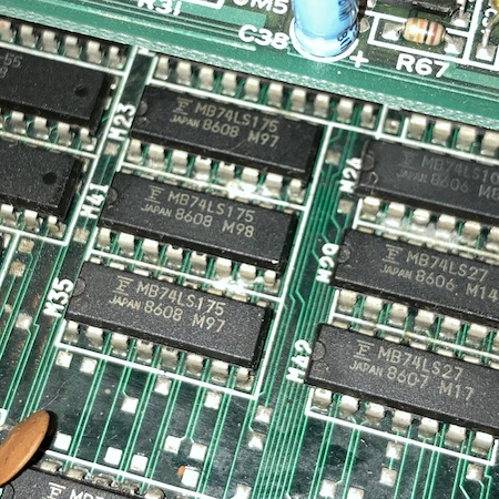
I was very happy to see that, unlike the NEC machines of the era, Fujitsu has very thick, clear, and easy-to-follow traces. Thank you to whoever did this board layout.
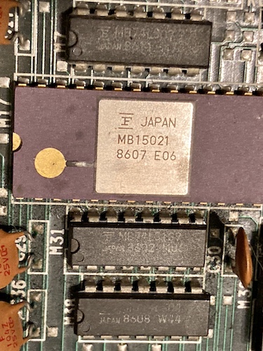
This seemingly-proprietary MB15021 video DAC IC1 has a little bit of corrosion damage to the gold strap on the top. Not being familiar with ceramic ICs, I wasn’t sure if that was actually a functional element of the chip, but it was definitely suspicious as being the cause of the analogue video problems.
Not seeing any particularly dramatic corrosion on the top side of the motherboard outside of the DAC, I wanted to look at the underside to see if anything had been pooling down there and wicking up the legs.
Removing the motherboard from the case is another project, because there’s a bunch of small-gauge cable running everywhere that is not loomed or braided together very well, and there are insufficient channels in which to place it. I ended up cutting a lot of zipties, and hoping that I remembered where they went when it came time to put the computer back together.
I lost count of how many screws and shields I had to remove from this thing in order to get the motherboard out. No wonder it’s so damn heavy!
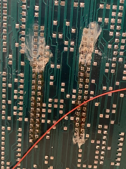
Surprisingly, the underside of the motherboard looked perfectly clean. I took the board over to the sink and used the boar hair brush along with mild dish soap to clean off all of the grease. Although the brush kept coming back from the board pitch black, I made some really good progress even on the first pass.
For the white gunk on the underside, I first tried to use isopropyl alcohol and a water flush, but the white gunk would keep coming back as soon as it dried.
For the metalwork, I used Spray Nine all-purpose cleaner and a firm toothbrush, which dislodged most of the ugly stuff. While doing this, I found out that the gunk near the card cage door was actually some kind of sticky thick clear-brown substance – not flux, not battery leakage. No idea what this was.
Now that I was reasonably happy there was no catastrophic corrosion damage, I wanted to try and power on the computer and figure out what wasn’t working.
Beep Beep I’m A JP21
In what seems like a betrayal of the ideals of the era, the FM-77 doesn’t have a Japanese 15-pin analogue RGB video port, or even a DIN8 one for digital RGB. Like some MSXes and MSX2s, it has a JP21 RGB port instead.
JP21 looks like the good old SCART connector, and in fact it mechanically is, but the pinout is significantly different. Since I didn’t have a JP21 to VGA adapter on hand, I decided to make one up using scraps I had on hand.
Unlike VGA and like SCART, it appears JP21 sends composite sync, where the horizontal and vertical sync signals are combined into one signal. This is sort of unusual for a computer monitor, but obviously more common for television.
Although I know my NEC MultiSync LCD can process a combined sync on the horizontal sync pin, a lot of other monitors can’t. Why not do things the right way and split them up if they’re going into a “VGA” sink?
I used the very popular (and surprisingly expensive) Texas Instruments LM1881 sync separator to split this combined composite sync signal into horizontal and vertical syncs, then fed them to a VGA port along with the colour data. Realistically, as this is a 15kHz signal, it’s not “really VGA” – but I already had the VGA footprint on hand from other Japanese computer video-out projects, the cables are cheap, and I had a bunch of leftover (also expensive) connectors to boot.
So how did it go? Well, considering this was my only working computer with JP21, you’re about to find out.
Test Fire One
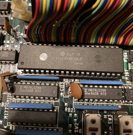
I plugged the motherboard in (without the floppy board connected) and fired it up. My LCD monitor, connected through the JP21 adapter, did not seem to find a signal and would not come out of sleep mode. When I applied the logic probe to the test point I had marked as “composite-sync,” there was no activity, just constant high.
However, it seemed like address bus stuff was happening on both the main 6309 and the 68B09E sub-CPU. The BIOS ROM closest to the main CPU was getting both output-enabled and chip-selected periodically. Using my logic probe, I poked at a few Fujitsu-branded buffers in the area of corrosion damage, but didn’t see anything particularly obvious.
I connected the PVM to what I thought was the composite-video RCA jack in the back, but nothing was produced. I would see a dim flash at power-on indicating a DC offset, but no sync latch or output. Later, I found out that the text on the back of the machine actually said “audio output.”
On the advice of Soji-san, I checked the hsync and vsync pins on the digital RGB connector on the back. This connector is a very pleasing-looking female DE9. Supposedly, v-sync was to be seen on pin 9 and h-sync on pin 8. And indeed I saw a lot of activity on all four lower pins, which told me that something is happening – the computer is generating some kind of video.
To figure out what was going on with the digital RGB connector, I decided to make a simple digital RGB adapter. Like the one on the PC-8801mkII, this adapter just steps down the TTL-level colour signals to something much lower that a VGA monitor would prefer, using 150Ω resistors. Here is the GitHub link to the FM77AV2 digital RGB to VGA adapter, with Gerbers so you can order your own.
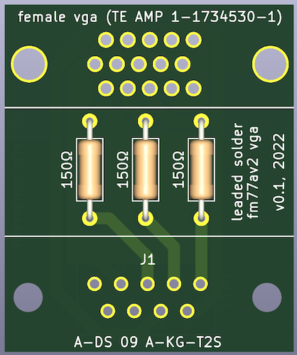
I’d have a better picture, but I’ve misplaced the actual board in the months since working on this computer. You know how it is.
At first, I was going to make this adapter using a screw-terminal hood, like the adapter on the X1turbo, but I couldn’t find my bin of VGA cable cutoffs. Like most of my life, I was already in the process of ordering some boards, so I decided to pay JLCPCB a few dollars and set the machine aside while I waited for the adapter PCB to arrive.
Test Fire Two
When the digital-RGB adapter board arrived, I quickly threw it together – with so few parts, I had everything on hand. As soon as the machine was powered on, the NEC 1970NX monitor I use on my bench lit up and latched onto the signal.
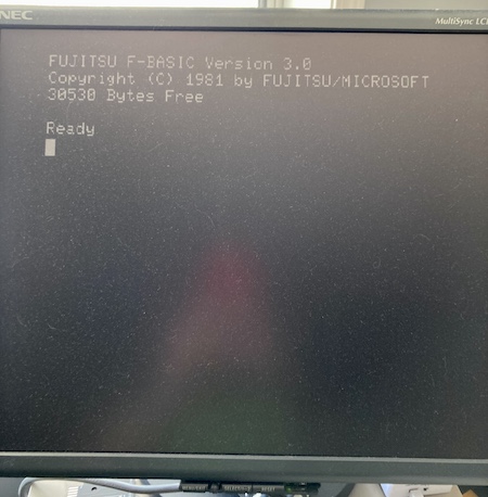
Holy crap, we have a working computer. So what’s actually wrong with this thing?
JP21 Gun Salute
At first, I assumed the problem was with my homemade JP21 adapter. After all, I don’t really know what I’m doing, and it seems more likely that the people at Fujitsu did know what they were doing.
I realized that the logic probe was probably the wrong thing to use to look for the 1Vpp composite sync signal, and reached for my scope. This would also tell me if the signal was getting stepped on, malformed, or otherwise just too weird for the monitor to accept.
To start out, I scoped the sync and blue pins at the JP21 connector. Both of those pins produced a pleasing square wave with nice sharp edges. Output was coming out of the Fujitsu, so what did I do wrong in adapting it?
Confused, I buzzed out the SCART male-male cable I had grabbed to use with this adapter. Being a newbie to SCART, I did not realize that a seemingly “straight-through” cable actually crossed over a bunch of signals for daisy-chaining purposes. I made some bodges to try and put those signals back in the right place, and soon had a nasty board full of junky soldering that still did not work.
At this point, I started getting confused about the various bodges I had made, and wondering if I had gotten the JP21 pinout upside down or reversed. Power to the LM1881 seemed quite low, at around 300mV, so I bodged a USB cable directly into it to provide that power. Now, the monitor would wake up, claim “out of range” a few times, and then go to “no signal” and turn itself off. Still, that’s progress.
I decided I would merge what I had done into a version-two board (with configurable jumpers!) and order it. I built that board, and it still didn’t work. I resolved to chase the video output chain from the FM77 to figure out what was broken. Then, I decided that sounded too much like work, and I already had “some” working video, so I moved on to more fun things.
No Re-Assemble, Solderie
At this point, I figured it would be a good idea to see if the machine worked when reassembled. Unfortunately, as soon as I re-added the “FDC/Sound” board, which is required for the front panel, the computer stopped generating working video on startup. The fan still ran, and it seemed like it was doing something, but the monitor would never wake up on digital RGB.
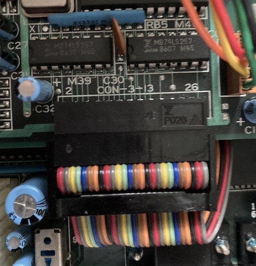
Because I had been testing as I re-assembled the machine, I started unplugging cables until it worked again. The culprit was the “CON 3-13” connector, a 26-pin ribbon cable going into the front-right of the FDC/Sound board. When that cable was unplugged, the computer would start up to BASIC, and when it was plugged in, the computer would not put anything on the screen.
Just to be sure the computer wasn’t blocking while waiting for it, I plugged in a floppy drive to the FDC board. The floppy drive seeked to track 0 on startup, but nothing else changed.
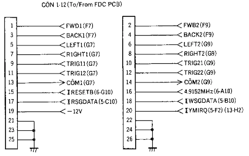
I looked in the FM-77 schematics, but there was no “CON 3-13.” There was a 26-pin connector going to/from the FDC board, called “CON 1-12.” And the signals appeared to be mostly joystick-related, which made sense because the ribbon cable is very close to the front-mounted joystick ports.
My assumption was that, when provided with one of these signals, something on the FDC board was holding up the startup sequence. An obvious first candidate was , which appeared to be an interrupt request line issued by the YM2203 when its internal timers fired.
I decided that I would pull CON 1-12 out of the plug and jump all of the suspicious lines across with Dupont jumper wires. That way, I could pull them out one at a time, and when the computer started working again, I’d know what signal it was that was holding the computer up.
Pulling didn’t do anything, to my surprise. Working down the list, I finally pulled – and the computer came alive, but everything on the sub-board still stayed stuck in reset! Something on the FDC/SOUND board was holding up reset!
Reset My Head
Fortunately, the schematics told me which parts of the sub-board consumed the signal. Unfortunately, it was virtually all of them: eleven chips, ranging in complexity from a simple 7474 to the YM2203 to the big MB88551-701N microcontroller QFP.
I wasn’t sure how to tell which chip was driving the erroneous signal. Maybe there’s some kind of test equipment for this specific task? I dimly remember a tool called a “current tracer” being mentioned from YouTube. Either way, I didn’t have it, so I did the next best thing, and started desoldering 74 logic from the board to test in my TL866. This board has generous pads, slightly oversized through-holes, and a very thick solder mask, so I thankfully didn’t have to worry too much about pulling pads and traces.
Every piece of 74 logic passed in my TL866’s Logic Test, so I started moving onto the more complex chips. Everything involved in reset with a DIP was desoldered from the board, a socket installed, and then tested with the chip removed but attached to the FDC/Sound board. It still remained stuck.
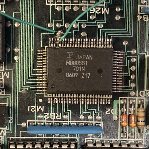
Finally, I came to the part I was dreading: the surface-mount MB88551 QFP. I determined that this must be the keyboard controller, based on the signals going into it on the schematic. Because I didn’t want to desolder it, I simply cut the trace leading to its reset pin and fired the machine up. It ran!
Great – a custom microcontroller with mask ROM has a glitchy reset pin and is driving the reset signal for the entire computer. I love this. Upon reading the relevant schematic, I found out that the MB88551 microcontroller’s pin could be configured as either an output or an input. Surely the original machine had it configured as an input, and something had gone wrong inside the package, maybe from whatever corrosive nastiness leaked onto this pin in the past.
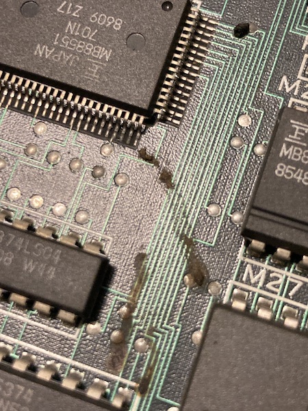
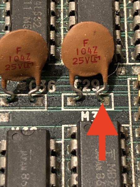
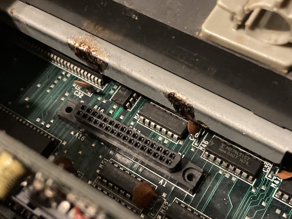
Now recall this earlier picture where a bunch of black likely-corrosive death was lying right next to the 88551:
That really gronky looking pin with the via very close to its pad? That’s , baby. Something’s gotten in there.
I cleaned around the area to make sure it wasn’t shorting to any adjacent pins, but it didn’t seem to be. I am still not confident enough in hot air to remove this part entirely.
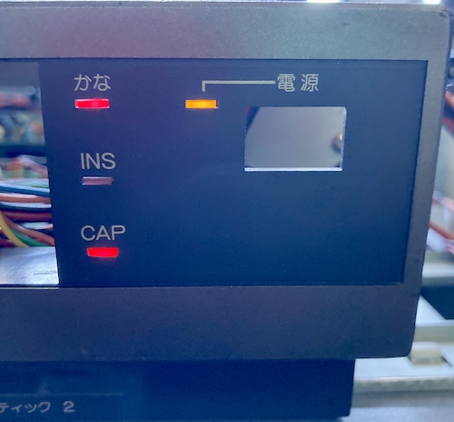
So now I was in a bit of a pickle. With the 88551’s signal detached from the system, I could now start the computer up. Unfortunately, without the keyboard controller, some oddness is to be expected. For instance, the kana and caps lights were lit all the time, when it seemed like they should extinguish shortly after startup:
The keyboard also was unlikely to work, even if I had one, which provided a further impediment.
I pulled the 88551’s reset line up to +5V with a bodged-on 33kΩ resistor, but there was no difference. It still stayed annoyingly low. The same happened with a 2.2kΩ resistor, showing that whatever output circuitry was driving reset low on the micro was pretty strong, and fighting it was more likely to damage the microcontroller than fix things.
I was ready to give up, but then I tried again with 560Ω. That moved it to +2V, which is in the right direction. I knew that the “high” switching voltage, Vih, for CMOS was roughly 2/3 VCC, so I needed to hit something around at least 3.3V? Let’s see where we get to with something a little more forceful…
Pulling it up with a stronger 75Ω seemed to make things less consistent. I was starting to see a weird white screen at startup, or garbled video, but the kana and caps LEDs were turning off after startup, indicating that the 88551 had come out of reset and was starting to slavishly obey its internal programming. Occasionally, the machine would crash and stop displaying video (not even sync) or seem to restart BASIC. Sometimes during this no-video tantrum, I’d see the kana and caps LEDs flickering very quickly.
I checked for shorts and bridges and unusually high resistances from my crappy bodgework, but found none.
Looking at the scope, the level at the reset pin hovered sort of close to 3.2-3.6V, which seemed like it could potentially be a little ambiguous for “high” or “low” input levels, and digital logic is renowned for its dislike of hovering around “I dunno.” I swapped my pull-up out for a much stronger 33Ω resistor, as that’s what came out of the pile of resistors first, and the symptoms seemed to, if anything, get worse, although the reset level did rise to around 3.9-4.2V, which is pretty decisively “high” in my book. However, the glitchiness didn’t really go away, with only about 1 in every 3 startups causing the front panel LEDs to extinguish. And I had no keyboard – whether IR or wired – to test it with.
I now suspected that I had cracked the “make it not reset anymore” code, but my timing needed work. My guess was that my little hack circuit wasn’t holding the 88551 in reset long enough, or not resetting it properly, which meant that it was waking up in a bad state. Either it was crashing the sub-CPU (which caused the crazy graphics and reset?) or just misbehaving in general (which caused the bad LED behaviour.)
The MB88551 seems to do a whole lot inside the system that isn’t strictly related to keyboard shenanigans. According to the relevant schematic, it is also related to real-time clock, and can drive both the main and sub-CPU data buses. The firmware on it is likely to be pretty complicated!
Keybodging
I didn’t want to throw out the entire computer, sick as it was, for the sake of a single keyboard controller. Hell, it was on a sub-board, and almost all of the parts except the keyboard controller were fine.
I sat down with a notepad, and came up with some ideas:
- Remove the 88551 entirely, and try to black-box duplicate its function with an RPi Pico or something, without an intimate knowledge of its ROM function, a working reference FM77AV2, or even a keyboard to test against;
- Remove the 88551 and send it to someone to be decapped, so at least we knew what was in the ROM, then use the 88551 datasheet to write a disassembler, reverse-engineer the disassembled ROM, and then port the whole mess to an entirely new floppy board using a different microcontroller;
- Give up on having a keyboard and only play games that use the joystick;
- Strip the machine for parts;
- Develop a better reset circuit for the MB88551 alone, using what I learned from using the 33Ω resistor to force reset.
Although the first two ideas sound like the most “fun,” the last one seems to be the easiest next step. My guess was that using the resistor alone was not working because it didn’t hold the chip in reset long enough to get its brains in order. I didn’t really understand how a “timed” circuit like this should work, so I asked a friend. Chartreuse showed me a few different circuits that might work, including this one from his 6800 homebrew:
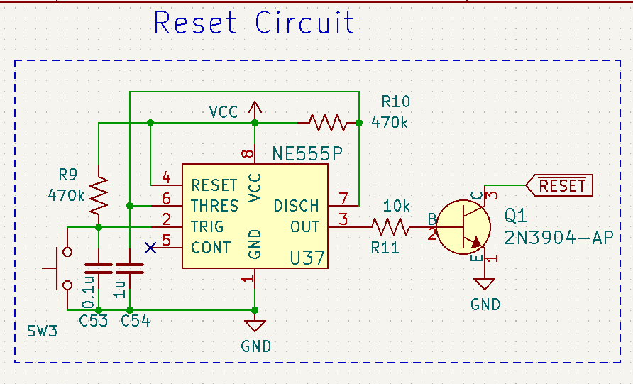
This design uses a 555 timer chip to hold an active-low reset signal at power-on for a little while, and use an NPN transistor to drive the actual reset line. I plan to build something like this, but I’m also still kicking around some of the other ideas.
I’m not confident that this bodge would be safe long-term, either: there’s a good chance that whatever is driving this signal is going to get really mad that it’s being forced up with a very strong resistor. Every time I start thinking about doing it, I get cold feet.
If you’re willing to decap and read out this ROM, get in touch – I’ll send you the whole floppy board.
Inconclusion
For now, the FM-77AV2 sits on my storage shelf. It’s been there for over a year. Its bulk and complexity makes it too annoying to leave out on a workbench, and I’ve moved onto other machines.
Although I have no idea why the analogue video output is not working, I suspect it may be related to the video DAC (even though I reported blue as being present, I’m not convinced that I remembered this correctly.)
I have recently just found another FM-77AV2, in order to try swapping parts over to resuscitate that part of the machine. They’re somewhat expensive (as are most Fujitsu 8-bit adjacent machines) but I think that it will be a worthwhile purchase if it helps me solve this mystery.
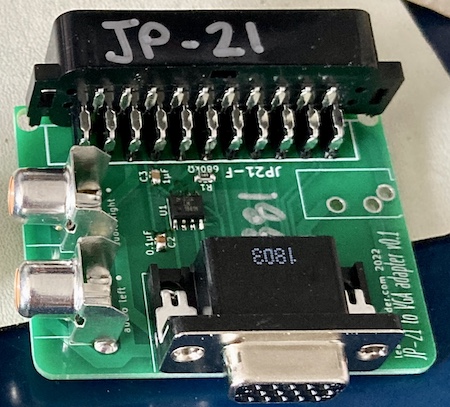
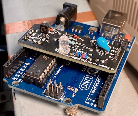
I still don’t have a keyboard, which I suspect might make reimplementing the keyboard controller a little bit more difficult. I have built Soji-san’s IR keyboard adapter (pictured below) but I think doing this as a hard-wired keyboard will be the easiest place to start for now.
While I’m waiting for the second FM77 to arrive, I have started building an implementation of this PS/2-to-FM77 keyboard adapter PCB. I am very grateful to everyone involved to making stuff.
Releasing this post is both a way for me to say “hey, sometimes this stuff is hard,” but also to motivate myself with ideas from the community about how to fix this problem. Like I said, it’s been on the shelf for a long time.
If this is an endemic problem to the 88551 mask ROM microcontroller, and not just ESD or someone spilling a bunch of bleach into a computer in storage, it will probably affect a lot of other systems in the future – not just my toy computers. In that situation, it would be essential to figure out a method to start documenting these mask ROMs and build equivalent parts before more of them become unusable.
Fujitsu of this era do not have a particularly good reputation in the arcade community because of other mysterious chip failures (reported to be bond wire corrosion or other package issues leading to failure – please comment if you know more,) and it would be sad to not have a substitute for these “custom” chips in order to keep FM-77s on the road.
Thanks for reading!
Repair Summary
| Fault | Remedy | Caveats |
|---|---|---|
| System does not produce legible analogue video. | No fix yet. | |
| System does not produce any video. | Cut stuck reset line on keyboard controller. | No fix for keyboard controller yet. |
-
The MB15021 video palette DAC is also used in the regular FM-7, so maybe I can try a swap. ↩