Composite Companion
Tags: console homemade-hardware bbc bbc-bridge-companion mod capacitors
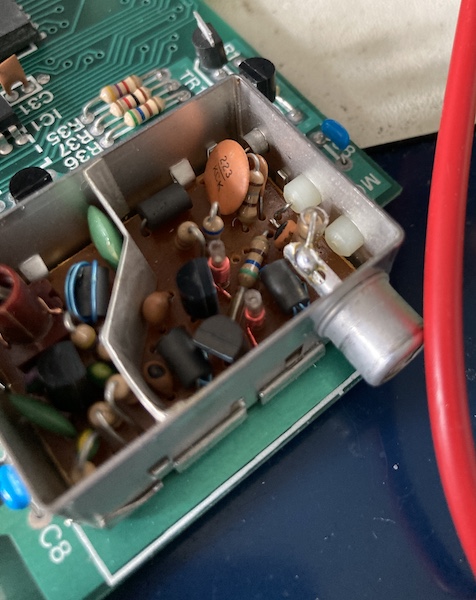
The BBC Bridge Companion has RF video output from the factory, but that’s not good enough for its cutting-edge pastel graphics. In order to get things looking their best, I spent a really long time making a composite video mod for the system rather than finishing off my Tetris clone.
Reaching into my pile of old homemade boards, I pulled out a second-generation Famicom AV mod board1 and assembled it with a THS7316 video amplifier IC. Obviously, I skipped the audio components, and then hardwired in a yellow RCA female jack. Some ultra-cheap test hooks later, and I had a pretty decent unamplified-composite-video probe!
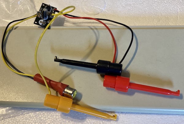
Using this, I figured I’d be able to hook the probe into various spots on the motherboard. By trial and error, I could work out where to grab composite video from before it goes into the RF modulator.
New Scope, Who Dis?
Of course, none of my candidate points for picking up a video signal seemed to work. I was a little confused, so I shelved it for awhile and then picked up a new oscilloscope2.
Before we get started, it’s worth pointing out that I still do not really understand composite video termination. That will probably become really obvious as this article proceeds – I’ve gotten better, but there is so much to learn about baseband that I still feel very uncertain about all of my initial findings and conclusions. Be gentle.
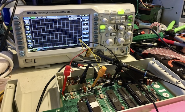
The Tek 2246 I’d been using is great, but it’s just too big and runs too hot for little projects like this. Even in the winter, it turns the room into a sauna. I got a Rigol for cheap to help with this project. It, too, boasts a PAL video trigger mode that seems like it would come in handy.
Almost immediately, I saw part of the problem with my little composite probe. When scoped, the output was only a handful of mV. When I was blindly connecting my composite video probe to everything I could find earlier, I had hooked it to pin 12 (“Video Input”) of the LM1889… but the scope told me that pin 12 had a 13.2V signal. The THS7316 amplifier datasheet says it has an absolute limit of about 5.5V input, which means I probably sent that little chip to silicon heaven. That would certainly explain why I wasn’t getting valid composite video out of it. Oops. I guess that’s why they make oscilloscopes, so you can measure first before plugging things in.
On the input to the RF modulator box, I saw a signal that looked like composite video, but it had a voltage of 1.86V to 3.18V. After asking some questions about it, it was determined that I was probably measuring it wrong. Since the output of the video was not connected to a TV, the 75Ω load that a TV usually puts on the line was not present. I ended up ordering a 75Ω BNC terminator and a BNC tee to bolt onto the probe, and took the measurements again.
With the terminator installed, I was now reading a more reasonable 2.49V peak-to-peak. This obviously isn’t ideal. From what I was reading, you want to aim for more like a 1Vpp signal, where 700mV of that is the colour and about 300mV of that is the sync dip when showing a pure white screen. To make matters worse, I was measuring the “No.” screen. It’s a very yellow screen, so I’d have to go by the sync amplitude to dial the divider in instead of aiming for the 700mV of white or the 1V of the whole signal.
I hacked up another Famicom AV board, adapting it onto a solderless breadboard with pin headers, and set up a simple output circuit. The first voltage divider I came up with (1.5kΩ/2.2kΩ) produced a 560mV sync signal, which was clearly way too strong. After asking blog friend Tianfeng for help, I put in a 1.5kΩ/470Ω divider at his recommendation, which knocked the sync down to about 300mV.
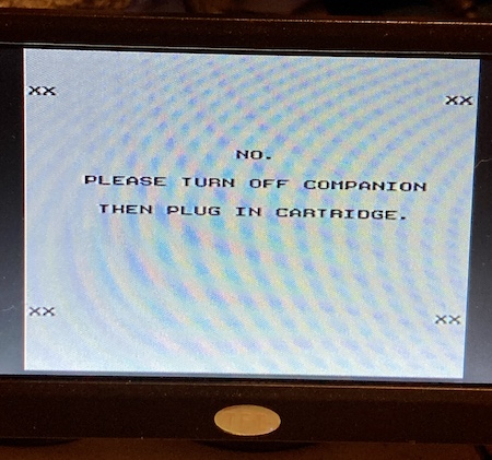
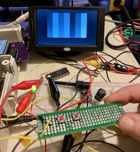
I couldn’t resist trying it on my backup camera monitor. You’ll notice it’s in monochrome. This monitor is super picky with signals and won’t lock on to a colour burst or vertical hold from any TMS99xx-based system, any Sega Genesis, or several other machines I’ve tried. It simply seems incapable of doing 240p at all. So why keep using it? Well, it’s small and easy to set up… and I don’t care if I blow it up.
Building Test Software
I was on my way, but now I needed a way to get a pure white screen to test against, in order to make sure my voltage divider will provide the right levels when presented with whatever output voltage the console generated for ‘pure white.’

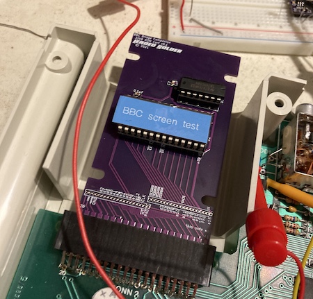
With about an hour of work, I modified my in-development Tetris program to generate various colour-test screens instead of addictive puzzle games. This new ROM displays solid white when it starts, and pushing the PASS key on top of the BBC Bridge cycles between screens of different solid colours. Pushing the SPADE button will toggle on some sorta-SMPTE colour bars (see above.) This new program was burned to a 27c512 EPROM, and placed into my bodge-wired new ROM board.
It’s running, so let’s break out the oscilloscope.
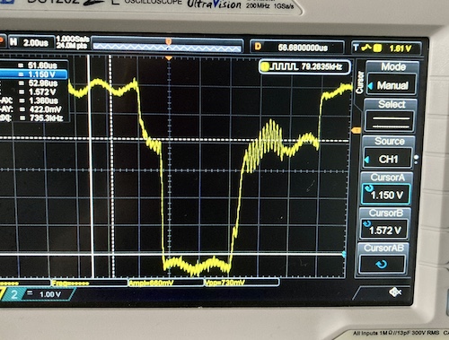
Oh man. That looks like a lot of power-supply ripple. I had never built a video circuit on a solderless breadboard prior to this, so I wasn’t sure if the noise was coming from the extra capacitance of the breadboard, the Bridge Companion, or somehow from the bench supply powering the console’s original linear 7805. Even clamping 100µF and 0.1µF decoupling capacitors onto the 5V supply lines of the mod board didn’t make a sigificant difference.
Did You Have Fun At The Mixer?
After poking around the board with the scope probe, I figured out that the ripple was coming from some of the 12V-related signals on the LM1889. 12V on this machine is generated internally from the relatively calm 5V supply, so something wasn’t quite right in the boost circuit. Bravely, I decided to ignore it until later.
It was difficult to find somewhere good to snipe the signal. As already mentioned, the final stop before the RF box had very dim colour. Working backward, I found that the chroma (colour) and luma (brightness/sync) were mixed on the board just by shorting them together, which was a bit of a surprise.
That chroma was still too weak when it arrived at the output circuit, because it was mixed at nearly 1:1 with the luma, which made it hard to divide into 1.0V total without making the colours way too dim. I needed something closer to a 2:1 chroma:luma ratio, in order to try and hit the 2:1 colour:sync ratio that a good composite signal should have. So I started trying to figure out how the LM1889 worked.
It was at this point that I remembered this unit was the very same Bridge Companion that had screwy RF colour, a lot of video noise, and tuned itself to the wrong channel. I decided it might just be a good idea to replace the handful of aluminum electrolytic capacitors involved in the system’s operation.
| Position | Capacitance | Voltage | Comment |
|---|---|---|---|
| C3 | 10µF | 50V | |
| C10 | 100µF | 10V | Fishy smell |
| C12 | 10µF | 50V | |
| C13 | 10µF | 50V | |
| C15 | 10µF | 50V | |
| C19 | 10µF | 50V | |
| C21 | 10µF | 50V | |
| C23 | 10µF | 50V | |
| C25 | 10µF | 50V | |
| C37 | 100µF | 25V |
I did this before I got my nice ESR meter, so no scientific proof of cap failure for you. Just vibes.
After the recap, I lost confidence in my composite-mod building abilities and shelved the project for over a year. I didn’t even test the recap.
Starting Over
When I came back to it, I tried reconstructing the composite mod on a solderless breadboard, following the Texas Instruments “AC-coupled” design specifications. This involved remaking some cables, because most of my jumper wires had been popped off and used for other projects.
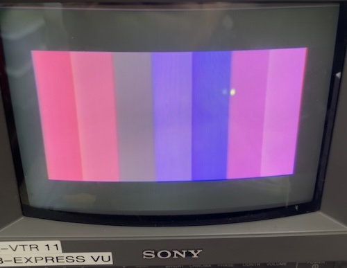
Colours! That’s good enough video quality for me, especially considering the green gun is not really working on this PVM3. After some measurements to figure out the dimensions and mounting points of the original RF modulator, I made up a quick PCB that duplicated the circuit from the breadboard. I don’t think that shotgun-recapping the system was really what was keeping my composite mod from working before, but it made me feel a bit better.
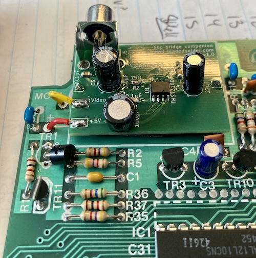
There were a lot of little things I had to mess with to get the physical alignment right. I’m glad I left room to slip it around for left/right, up/down, tilt. After all that, I was mercifully ultimately successful in getting the port to point out of the hole, such that the composite video cable could still fit into the much smaller opening when the lid of the console was put on.
I also went back and touched up that fraying +5V jumper wire, don’t worry, you can trust me.
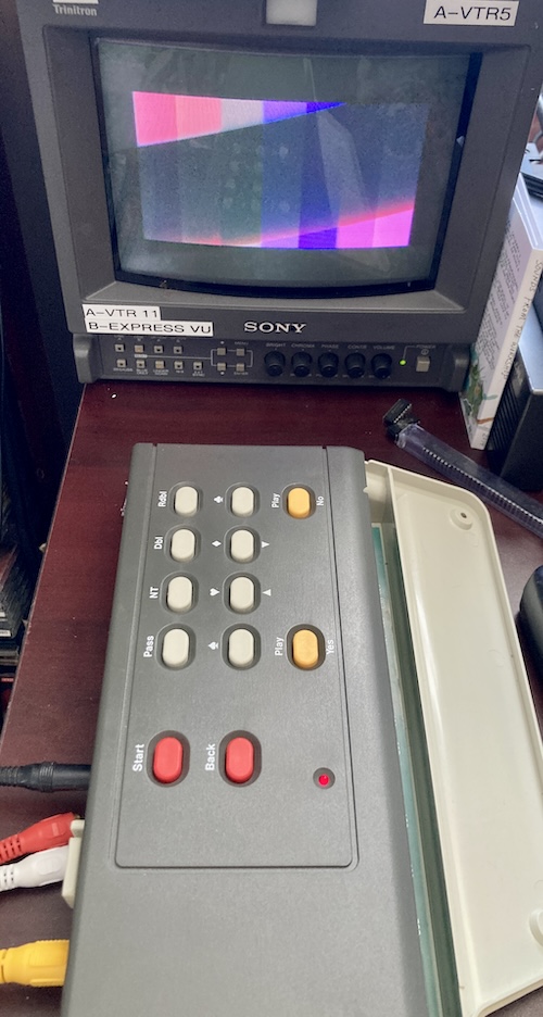
It fits! Nice.
Composite Conclusion
Making an AV mod for this system wasn’t as hard as I had originally thought it was going to be. Maybe it’s because my standards slipped. But there is one solid lesson I learned: if you see a lot of ripple on the scope when you’re trying to dial something in, swap the caps already. It’s a lot easier to work from a known-good base than add that extra frustration for a repair that literally took ten minutes to do.
Repair Summary
| Fault | Remedy | Caveats |
|---|---|---|
| (1984 unit) RF video output seems unstable, noisy. | Recap system. |
-
The big difference between the 1st and 2nd gen Famicom composite mod is the presence of the 75Ω output resistor. The 3rd generation, which I wrote about in Revenge of the Famicom composite video mod, is just a smaller version of that board with an integrated voltage divider circuit. ↩
-
Most long-time readers have probably seen me use this scope before. The work in this post was done almost five years ago – I have greatly procrastinated on writing up and publishing this series. ↩
-
Long-time readers will feel reassured that in the several years since this work was done, I still haven’t fixed the PVM. Thing will keep running pink as a pig until it bothers me enough to deal with one billion caps in a box about the size of a coffee mug. ↩