Revenge of the Famicom composite video mod
Tags: console nintendo famicom mod homemade-hardware
When we last read about the Famicom composite mod, there were a bunch of changes I wanted to make, but left tragically undone in the name of getting in some Mario time over the holidays. Now I’m going to make a solid effort at producing a more production-ready version of the modification.
There were several problems with the Famicom mod from last time:
- The output is a little bright, because my input voltage divider circuit could have chosen better values for its resistors;
- There’s a distinctive blue “push,” which seems to overpower the other colours on the screen, especially in games like Super Mario Bros;
- The board received so many bodges that it has fragile dead-bugged resistors, kapton tape, capacitors and patch wires, which have crap soldering, melted insulation on the wires, and are all just waiting to die;
- I can no longer close the case on the mod, because with all the bodges, the mod board doesn’t fit into the little pocket between the RF box and the shell that it was planned to.
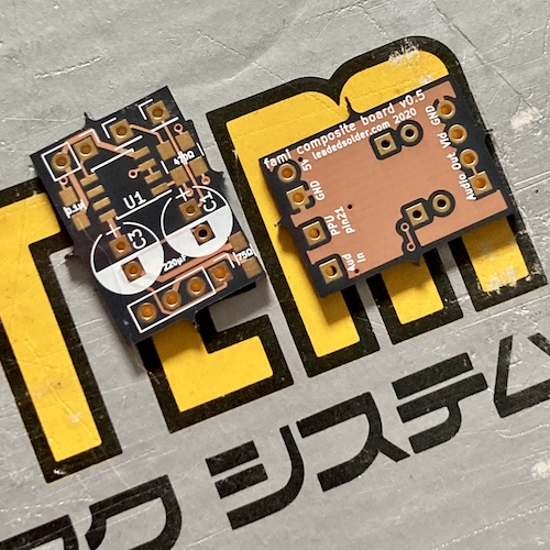
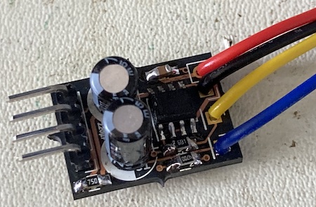
The solution to all these problems (I hoped) was the “v0.5” mod board, which I teased at the end of the last article but didn’t go into a lot of detail about:
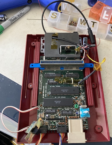
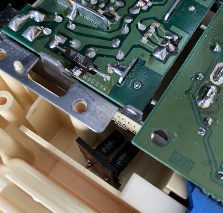
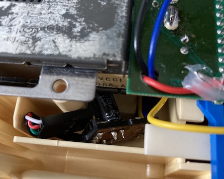
After adding some caps for a test fit, I determined that with the new board – as with the original, at least pre-bodge – problem number four is pretty much dealt with. There’s tons of room between the RF unit and the case in which to mount the board, run wires, and avoid any physical interference with the cartridge eject fork:
I also decided to try out the THS7316 this time, instead of the THS7314. They’re basically the same video-amplifier chip, except the 7316 doesn’t feature a low-pass filter. You don’t really need one for a CRT, and I also got a great, if suspicious, deal on them: five 7316s on eBay for what I’d pay for one 7314 on Digi-Key.
Deconstruction
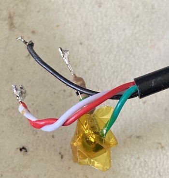
Although since the original entry, I have acquired a lot more Famicoms1, I wanted to do right by the original machine. As such, I meticulously desoldered all the old components and cleaned up the TRRS harness:
Family Computer (Voltage Divider) Values
I figured I would approach the too-hot video output by tinkering with the voltage divider on the 2Vpp input from pin 21 of the Famicom’s PPU. Because chroma and luma are already mixed into the composite video by the time I get ahold of them, this will have the result of dimming the output overall. It would have been nicer to tune chroma and luma separately, but unfortunately that’s just not the design of the Famicom/NES PPU.
The voltage divider circuit in the previous model halved the voltage by using two resistors of the same value, 470Ω, producing (I thought at the time) the 1Vpp value that the composite video “standard” expects.
The equation for calculating the resulting voltage is pretty simple:
Vout = Vin * (R2 / (R1 + R2))
As an example, here’s what the old divider produced:
2Vpp * (470Ω / (470Ω + 470Ω)) = 1Vpp
The motivation for the values I chose were basically “which resistors do I already have on hand?” My goal was to find which combination of values produced a voltage divider that’s “pretty close” to half – I only wanted it a little dimmer, not completely dark. Since I don’t have a vectorscope with which to interpret the 240p test suite, I’m going to use the very unscientific method of guessing and eyeballing it.
Here’s some example values I considered:
| R1 | R2 | Multiplier |
|---|---|---|
| 1000Ω | 470Ω | 0.32 |
| 820Ω | 470Ω | 0.36 |
| 680Ω | 470Ω | 0.41 |
| 510Ω | 470Ω | 0.48 |
For experimentation like this, it’s nice to have a bunch of different values on hand. I got the 680Ω that I ended up using from one of those AliExpress “sample books” of 0805 resistors.
Assembly
Soldering the board together was straightforward but annoying. Because I put the through-hole caps in first, I had to work around their height when I was installing the surface-mount caps and resistors. It’s not my favoured method of assembly, but the test-fit from having the through-hole caps installed helped immensely, so let’s say it all evened out in the end.
The hardest part of this project is running all the wires. I need wires from the PPU’s pin 21 to get the composite video output, as well as 5V and GND, and the monaural audio. Luckily, in the previous entry I did all the work of finding those pins, so it’s just a matter of wiring them back up.
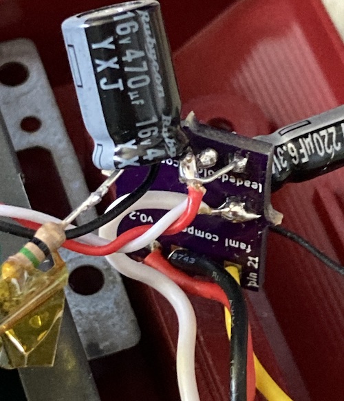
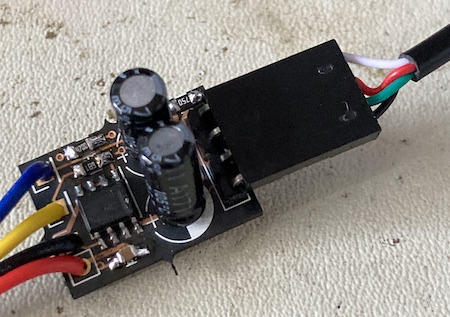
Because I wanted to be able to disconnect the TRRS jack in order to experiment with voltage dividers, I put a right-angle 0.1” pin header on the board and then crimped the TRRS jack’s harness for female DuPont connectors. This was probably a mistake; not only did I not need this extra flexibility, but the additional length of the DuPont shroud made the board so long that it was no longer an easy fit.
I decided to be fancy this time and experiment with using hot glue to tack down the wires for a cleaner, more reliable install. It was an enormous failure. I don’t know if the chemistry of the hot glue I was using was particularly crappy, or if the solder mask was too smooth for it to adhere, but every wire I tacked down popped off about 10-15 minutes after the glue cooled.
I regret having pulled the PPU pin 21 out; not only does it weaken the leg and present interference risk, but it also made it more annoying to route the yellow composite video wire from the front of the board without hitting the cartridge eject fork. I used a ziptie to retain it to a hole in the motherboard, but it’s not a clean job. My suspicion is that the “pull the pin” advice comes from getting a cleaner signal on the older transistor-amplifier circuits; I think it would have been better overall to have desoldered the transistor nearby pin 21 and soldered into its hole; the video amplifier IC can likely compensate for the little bit of noise introduced by leaving the rest of the circuit attached. Since I have another Famicom, it might be worth doing a different mod technique on that one.
I also used a piece of double-sided tape to hold the board up so it wouldn’t fall onto the cartridge eject lever when the Famicom was turned right-side-up again. Not sure how reliable this will be; I’m worried that the tape’s adhesive will become corrosive over time, or at least fail.
Test Fire One
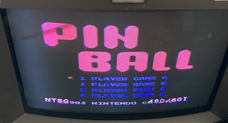
I put in Pinball, and after a small disaster where I realized I forgot to connect the ground wire of the mod board properly, the Famicom was up and running. The audio was still loud, and the video was still crisp. Of course, because of my tinkering with the voltage divider, the signal was a bit dimmer than before, but not unplayably so.
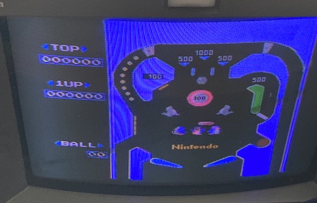
There is still a distinct blue push, but it’s a lot less noticeable than it used to be. The colours still look “off” here, because my PVM9L2’s green output is now aggressively dying.
After some more experimentation (read: games,) I determined that this was probably the right setup.
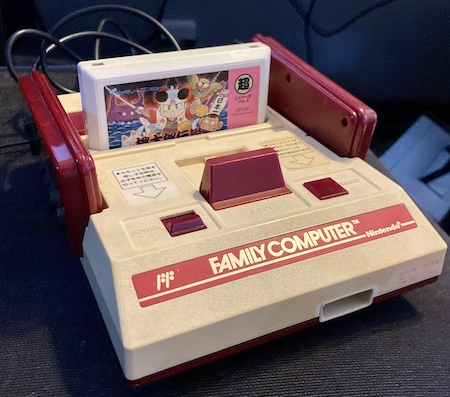
I screwed the case back together, did a few last-minute tweaks to wire routing to make clearance, and it looked like a Famicom again. Of course, in the months between the original mod and this one, I had lost a handful of screws and grommets, but they’ll turn up.
Conclusion
It’s not a perfect mod: I’m still worried about physical interference between the mod board and the eject fork, the dangly TRRS cable is ugly, and I think there is probably more to do with regards to colour tweaking.
Even so, I now have a working Famicom with composite video output, one that doesn’t require me to spread its guts across a table in order to play it and that I am not worried about accidentally dropping something into and shorting it out during a gameplay session.
With this mod, and some future maintenance, I hope that this machine can enjoy another 32 years of happy life. Now just to get that Disk System rebelted…
-
It’s a sickness. If you or someone you know is suffering from Too Many Famicoms, good. ↩