Companion & Companion's Cartridge Complication
Tags: console bbc bbc-bridge-companion homemade-hardware homemade-software repair
In this phase of the BBC Bridge Companion series, we’ll talk about a few simple tasks. Buying a system. Buying another system. Fixing both systems. And developing a cartridge PCB for them from scratch. Doesn’t everyone spend their weekends this way?
First, I’d been puttering along in the emulator, but had not yet taken the plunge on the real hardware yet. It’s expensive buying things from eBay, and even moreso when it’s another country’s eBay, trying to get a fair deal for their prized government-backed information technology treasures.
Oops, eBay
Initially, I really did not want to pay the eBay asking price of $175 for a Bridge Companion, and then also pay a huge shipping fee on top. I kept looking at eBay, but missed when a boxed and complete unit was listed. PeteG from the re-enthused Discord server noticed, knew I was in the market, and gave me the tip-off.
After a week-long bidding war, I scored that boxed Bridge Companion for £90 (about $145 CAD at the time,) shipped. This is definitely more than I planned on spending, but the lure of “cheap shipping” is powerful indeed.
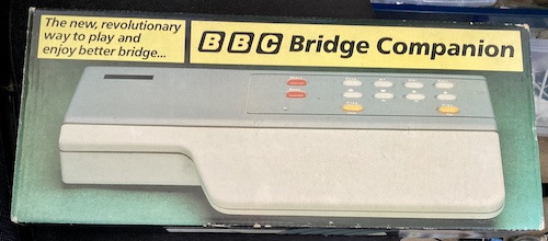
It arrived very quickly and it was extremely well packed. I was unwrapping bubble wrap for nearly ten minutes just to get the box out!
The overall condition was fairly good aesthetically; there was a slight discolouration of the plastic that will probably clean up with a scrub. Definitely not filthy. The buttons felt wobbly but not terrible, which is good since they were the only input mechanism in this console.
Unfortunately, during inspection, I found out that the cartridge slot has had a rough past life. A handful of the leaf pin contacts are either bent backwards or have popped out of their retainers entirely. Even after some work with an angled pick, cartridge contact seemed like it would be spotty at best.
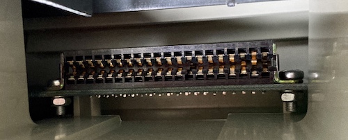
Check out the heavy hardware and reinforcement brace holding the slot in place! Now that’s some serious strain relief, which I guess you can do when you’re charging £199. Great build quality.
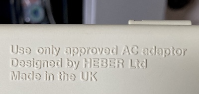
There’s no marking on the system of what the AC adapter voltage or polarity was; it just had this marking saying that I should use only the appropriate adapter. This lettering is very clear, and the case overall seemed like very well-done injection moulding. Again, good build quality, possibly helped by the fact that their tooling couldn’t possibly have gotten that many uses.
Heber is a contract manufacturer and hardware designer in the UK; they’re still around, and still make video game equipment, including casino game motherboards and the MiSTer Multisystem. I’m not sure what happened to Unicard.
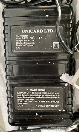
The 9-volt AC adapter included in the box is not really useful to me. It has a UK-style plug and expects 240VAC, and the polarity (or even whether it’s DC) isn’t indicated on the label. Additionally, the plug seems to have been added by the end-user1, as it’s “hardware-store grey” and has some repulsive sticky residue on the cord that might, at one point in the past, have been electrical tape. Surprisingly, the cord itself was still supple – it was the electrical tape’s plasticizer that was attacking the styrofoam around it.
After checking inside the machine with a continuity tester, I determined that this barrel plug was centre-negative (the centre pin of the barrel plug was connected to the “common” pin of the 7805 voltage regulator.) A Sega MK-1602 adapter (Model 1 Genesis/MegaDrive) fit perfectly and provided the necessary polarity, voltage, and current ceiling. It works with everything! Gotta pick up more of these little miracles.
Let’s take a look around while we’re in here. Don’t want to start if there’s something else wrong, after all…
Diagnosing the Companion
The first thing I noticed when taking apart the Companion is that the screws were a little weird. They’re coarse-thread Phillips thread-forming screws, to be sure, but the cross head wasn’t exactly cross – more resembling a wounded bird. I’ve never really seen screws like this before; maybe they’re made of a very soft metal and bent before camming out at assembly. I had to be very careful when removing or installing them not to strip out the heads any further. A future improvement would be to go to the hardware store and just buy new thread-chasing fasteners, as they appear to be all the same length and pitch.
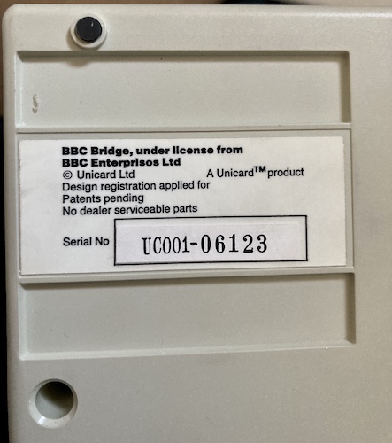
No dealer serviceable parts? That’s one step beyond Radio Shack. I don’t know what store you would have bought this at when it was new, but they were insufficiently skilled to repair a machine as advanced as the Bridge Companion.
My serial number was 6123. If they started at 0001, I guess we can assume there are at least 6,123 Bridge Companions out there. That feels like a safe bet, because mine seemed to actually be a revised version - different from the photos I’d seen on the internet beforehand of other Bridge Companion motherboards, and another Bridge Companion motherboard I would later have in my hands. But I’m getting ahead of myself.
Again, it’s worth taking another stop here in the story to reinforce that the plastic panels on this thing are of very high quality. Even though they’re thin plastic, the moulding is sharp, without flash or ugly casting artifacts, and the dimensions are nicely square. It makes me wonder if they reused an injection mould from another product to keep the tooling costs down – the buttons especially make me think of photocopiers.
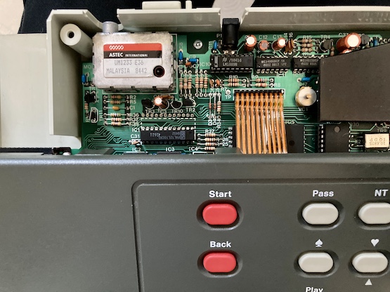
Once the plastic “chin” piece is removed, the top part with the buttons comes right off. It has a ribbon connecting it to the mainboard, but the pins are so thick that this ribbon pulls right out with no problems. Nice.
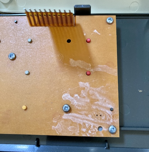
The front panel with all the buttons had this chalky white crap on the backside, which I think must have been leftover flux. It didn’t move very well with alcohol, so I had to keep scrubbing at it until it did.
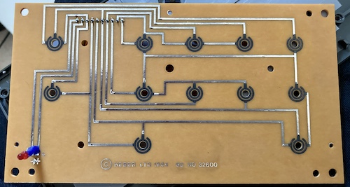
The control panel PCB itself (copyrighted 1984) is just a normal carbon-contact setup, and is shorted by a membrane that is itself depressed by the funky plastic buttons. There’s a power LED here, too, which is a nice feature… on a machine that doesn’t even have a power switch. I guess they expected you to switch it off at the outlet instead, which is not really a thing I could do here in Canada.
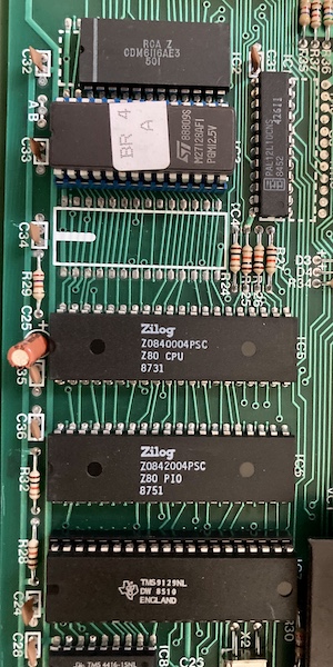
The routing on the motherboard is quite good. Now that I know how difficult it can be to do a clean route, the relative lack of vias is impressive.
On the motherboard, we see the big important chips. A Z80, 2kB 6116 SRAM, the BIOS ROM (a single 16kB 27c128 instead of two 8kB 27c64s like in the picture I’d seen earlier), the Z80 PIO, and a TMS9129 VDP with a pair of its own TMS4416 video DRAMs offering a vast 16kB of VRAM2.
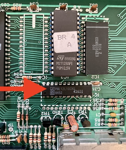
This 12-input/10-output programmable logic array (PAL) chip most likely contains the memory and I/O address decoding for the system. It’s interesting that the system is using UV-eraseable EPROMs instead of mask ROMs; perhaps production was too low to justify the expense of mask ROMs3.
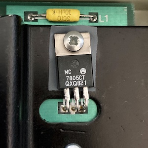
This 7805 produces 5V for the rest of the system. It’s also strapped to this handsome black heatsink which has a thick coating of some kind.
The RF modulator is your normal UM1233 setup, with no sound hooked up to it of course. I’m sure that the reason these modulators are so common is because they had to get them certified for radio interference. By using a whole module, Heber, Sinclair, etc could outsource the analogue-TV part of the compliance – and all the legal headaches that entails – to Astec.
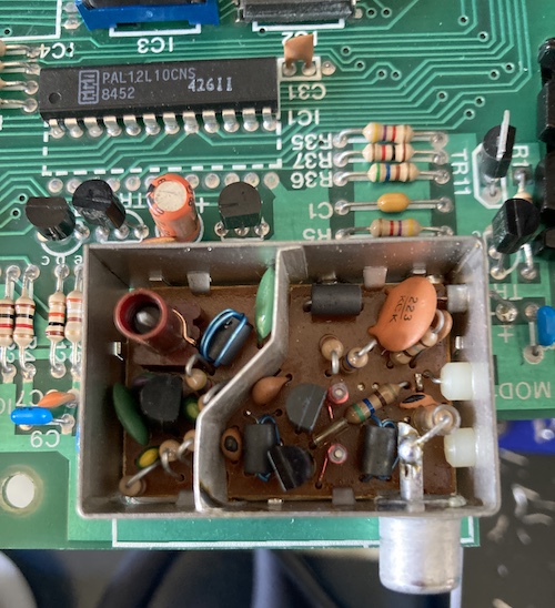
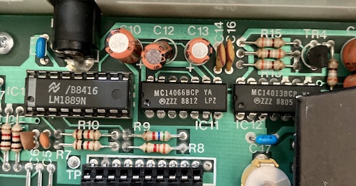
Near the RF modulator is a common IC in PAL game consoles of the era: the classic LM1889 composite video modulator (I know the name is a little confusing.) The area nearby also has an MC14066 quad switch, which according to the datasheet, is probably also involved in the output video circuit, and an MC14013 D-type flip-flop, which is maybe used as a clock divider or to alternate which field of the video signal is being displayed. I’m not very familiar with PAL generation, as this was the first PAL system I’d ever looked at the video output for.
Let’s take a look at the cartridge before we finish up. It’s a very unusual size that reminds me more of an electric razor than a game cartridge. Thick, narrow, and stocky…
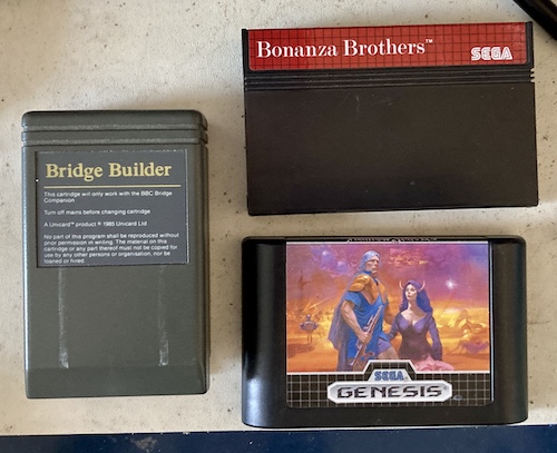
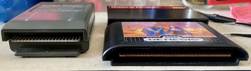
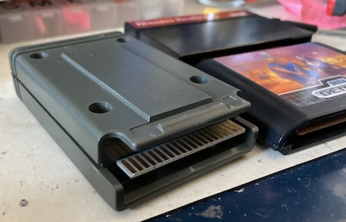
It also has a lot of unnecessary plastic “greebles” all over it that make it look a bit like a weird science fiction prop. There’s even an interesting “skirt” cutout on the back so you can see the gold-plated, non-beveled edge connector. The cartridge feels solidly-built and is made of thick plastic, which I’m sure helped sell the sense of being a quality product to the end customer.
I’d like to thank whoever at Heber decided that the screws should be exposed without having to remove the cartridge label, unlike some systems. Once the four screws are undone, the PCB pops open… look at all that empty space and super-shiny solder mask!
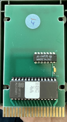
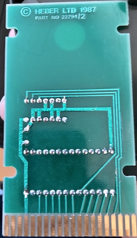
The only ICs in here are the socketed(!) 32kB 27c256 EPROM(!) and a 74ls08 AND-gate, of which most of the inputs are grounded. It’s interesting that there’s a 1987 date on this board. Since this game was packed in with my Bridge Companion, it would mean that they were still selling these consoles for at least two years after release.
That’s enough screwing around inside the machine for now; let’s move on to getting something to happen, even if it’s in PAL.
Video, Kid
Blog superfriend Nicole at Nicole Express published a great article on the Sears Tele-Games Pinball Breakaway TV game. Not only is it a fun anachronistic read, but you’ll also notice that she hooked up a fancy Chinese-made device called the RF-to-AV in order to make it talk to her composite capture rig.
Realizing an opportunity to get out of this without having to do a composite mod to the Companion on top of everything else, I sent away for my own and got it a few weeks later for under twenty bucks. The menus are completely inscrutable (all in Chinese that’s also somehow extremely blurry) but the price is right.
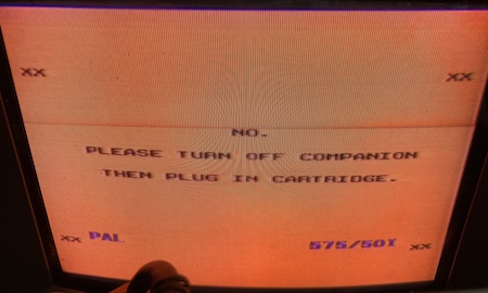
At first, I had some decent success locking onto a signal using my PAL-capable PVM. You can have your choice: with a hellish orange glow, or with a super-wiggly white background that appears purple because my PVM is crying for help that I refuse to give it.
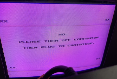
Both times, the PVM identified the successful signal as 525-line PAL, which I don’t think is actually correct for UK “System I.”
Eventually, I was completely unable to lock onto the signal after turning the RF-to-AV off and then on again. After wasting about an hour trying various combinations of standing on my head and cursing the gods, the best I could hope for was an out-of-sync image where I could just barely see smears that I knew were supposed to be text.
It seems (from reading other sources, including the seller’s ad) that the adapter’s “autosense” population of the channel selector is based at least partially on sound coming across the RF. Since the only thing the Bridge Companion is sending on the sound channel is ambient space noise, it’s not likely to work well with this approach. I could see the autosense routine slowing down as it approached 591MHz (“Channel 36” on UK System I,) but it wouldn’t realize a channel was actually there.
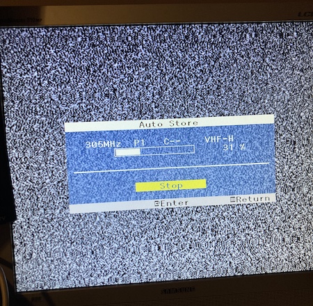
I ended up carrying the whole mess to another room and testing it on my Samsung 910MP, the gently-battered4 LCD TV that somehow is capable of getting a crappy image out of any source – but I mean it when I say any source. Since it’s a modern set, it can change its fancy little microchippy guts to understand RF from any region.
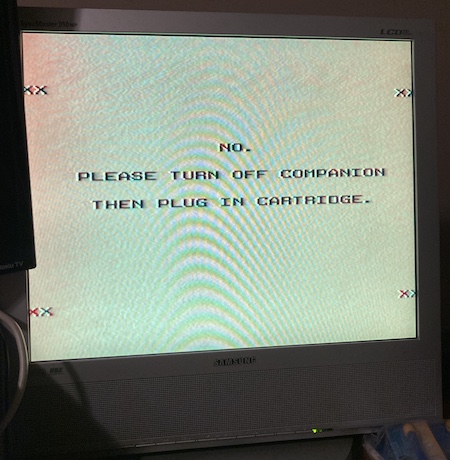
After switching the 910MP into “Europe/UK” mode and then auto scanning the channels, it found the Bridge Companion at 592MHz and plunked it into “Channel 1.” Now it’s a very bright yellow, rather than the emulator’s tan. Just what colour is this damn thing supposed to be?
I did a little more fine tuning to keep the image from wiggling, and now I finally had a sort-of-legible way to see this obscure PAL RF console in my largely NTSC composite home. But, uh, I didn’t like it.
Winning At The Slots
I didn’t expect I’d have to repair the cartridge slot on this machine, but that’s life.
Since the plastic shell of the slot, its long mounting pins, and the reliefs for the reinforcement braces all seem to be more than a little unique, it worried me that it would be a challenge to find a replacement part.
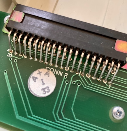
The solder joints on this slot were in pretty poor condition. If I hadn’t felt the screws on the case snap loose for the first time, I would have assumed someone had already tried to repair it. It’s an interesting contrast to the expensive cad-plated (or maybe just yellow zinc-plated) metal brackets holding the 2x20-pin connector down.
A brand new right-angle 2x20 0.1” edge connector did indeed prove hard to get. It doesn’t really make a lot of sense; I could even find 2x21s. I first grabbed a $10 Sullins from Digi-Key – the only one in stock – only to find out it had a death grip on the cartridge. Just like with the second failed cartridge slot used in the Leako, also a Sullins, I missed the part of the datasheet that said it could only handle 1.57mm thick PCBs and not 1.6mm ones.
There was a 40-pin, right-angle, 0.1” edge connector listed at Digi-Key by TE AMP, but it was listed as “submit a quote request.” For laughs, I did, and they came back and told me that they’d make some if I promised to buy a minimum of 2,688 units, at $5.10USD per connector. I can afford a lot of 44-pin connectors to cut up for $13,727.62 USD!
In the meantime, I found an eBay seller in Taiwan offering some connectors of an anonymous brand, so I bought a box of ‘em. This new mystery-meat connector still had a bit tighter of a grip than I would prefer, but it was still possible to insert and remove the cartridge with a lot of force, probably due to the cheap-feeling pins.
Initially, I was not comfortable with this fix, worrying that the extra force of insertion would damage the console’s board, but once it was completely soldered up it had a surprising amount of strength, and it got easier with repeated insert/remove cycles. For a little extra insurance, I also applied a thin strip of double-sided Gorilla Tape between the PCB and the cartridge slot, which is surprisingly sticky stuff, albeit quite thick.
With a shrug, I figured this was good enough to keep the project moving along. Since I was planning on making my own cart anyway, beveling the edge on it would make the cartridge easier to insert and remove, and thus compensate a little bit for the tightness of the new connector, and if the slot ended up pulling up a bit anyways, I could use my garage vise to bend up a new metal bracket and push the new connector down.
As for removing the slot, it wasn’t too bad. Originally, I planned on using the FR-301 desoldering gun, but I decided on a gentler approach when I realized the solder mask was damaged on the underside:
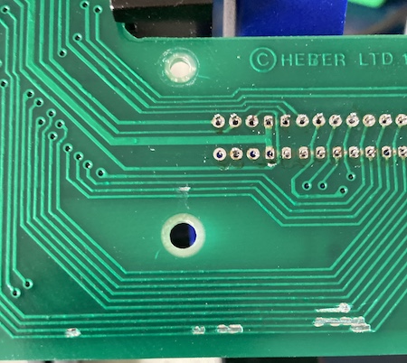
I ended up snipping each of the pins off the old cartridge slot and desoldering them individually. It’s not as pretty of a result, but the chances of pulling a pad or trace are much lower.
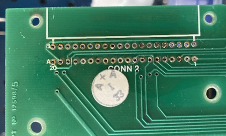
The old cartridge slot, of course, is not in the best condition after this treatment:
Sorry, I couldn’t resist.
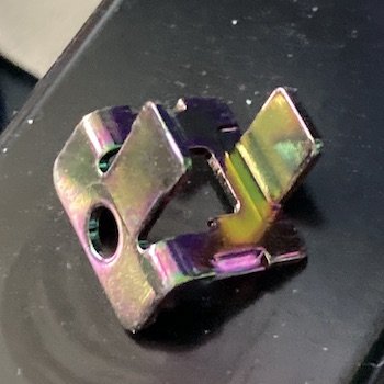
I wasn’t sure initially if the metal brackets holding the old cartridge slot down were zinc- or cadmium-plated, but this seems pretty likely to be cad-plating to me:
Yeah, Here’s The Cartridge Pinout
While the slot was removed, I had easy access with my multimeter probes to help map out the cartridge slot. Here’s what I found:
| B | A | |
|---|---|---|
| 20 | /ROM_CE Select 8kB bank 4 $0xa000 (PAL pin 15) |
PAL pin 16 |
| 19 | /ROM_CE Select 8kB bank 3 $0x8000 (PAL pin 14) |
Z80 IORQ |
| 18 | /ROM_CE Select 8kB bank 2 $0x6000 (PAL pin 18) |
Z80 MREQ |
| 17 | /ROM_CE Select 8kB bank 1 $0x4000 (PAL pin 19) |
GND |
| 16 | D3 | D2 |
| 15 | D4 | D1 |
| 14 | D5 | D0 |
| 13 | D6 | A0 |
| 12 | D7 | A1 |
| 11 | A10 | A2 |
| 10 | /ROM_OE | A3 |
| 9 | A11 | A4 |
| 8 | A9 | A5 |
| 7 | A8 | A6 |
| 6 | A13 | A7 |
| 5 | A14 | A12 |
| 4 | VCC | Z80 WAIT |
| 3 | PIO PA1 | Z80 CLK |
| 2 | Z80 WR | Z80 M1 |
| 1 | A15 | PIO PA0 |
Tons of useful signals here. A15 seems to be part of an input to the PAL, as well, which probably exposes some bank-switching ability for very large cartridges. Following the pattern, it’s very likely that the unknown A20 edge pin is meant for switching in a whole other bank, but Bridge Builder only goes up to a 32kB ROM and I definitely don’t need more than that for Tetris.
Obviously, this process is made more difficult by the opaqueness of the PAL itself. Without building something like a DuPAL board, I was probably not going to easily reverse-engineer it.
A Companion Companion
To muddy the waters even further, I still had an email notification on eBay set up for new Bridge Companions. One came up from a house-clearing firm, was sold as totally untested, and came with only the cartridge. I made an offer for £25, which was immediately accepted. A very good discount over £90.
The next day, PeteG (who, you may recall, started this whole mess) got one for £5, so I didn’t even get a chance to brag about my great deal.
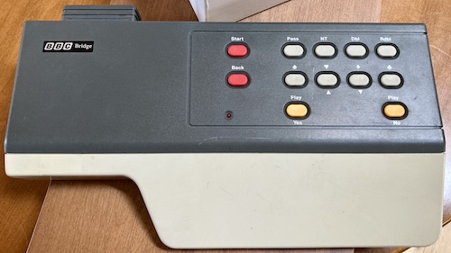
Why get another? Well, as my grandfather always used to constantly say, “whenever you’re building your own circuit board and trying to jam it into an old machine that you can’t easily get a replacement for, buy another one of them to mod.” He was a weird dude, but he didn’t steer me wrong on this one. Thanks, Grandpa.
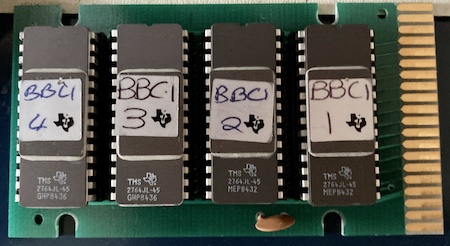
When it arrived, I couldn’t help noticing the differences. For instance, this one was serial number 00577! When I opened its copy of Bridge Builder up, it had a date of 1984 and the entire GDP of Great Britain in 64Kbit socketed ROMs. This is how I figured out the “8kB” bank switching in the pinout up above.
The Magic Happens
Through collecting two machines, I now had:
- A working cartridge slot in one of them (the second one;)
- A socketed cartridge that accepted 27c256 EPROMs (from the first one;)
- A television set that sort of worked to display the video coming out of these.
I burned my in-progress test ROM, which didn’t do much more than display a couple in-memory variables and put up the basics of a playfield along with “HELLO WORLD” esque messages to a W27C257 EEPROM (originally bought for the Leako project) and slammed it into the 1987 Bridge Builder cartridge. Thanks for the socket, Heber!
Unfortunately, the new Bridge Companion didn’t show up on the same channel as the old one! I had to re-scan channels again, and ended up with a very bouncy, glitchy output from the new one. It will need a service, but that doesn’t mean I can’t use it to test my game… on real hardware.
I popped the cartridge in, and then plugged in the DC power jack…
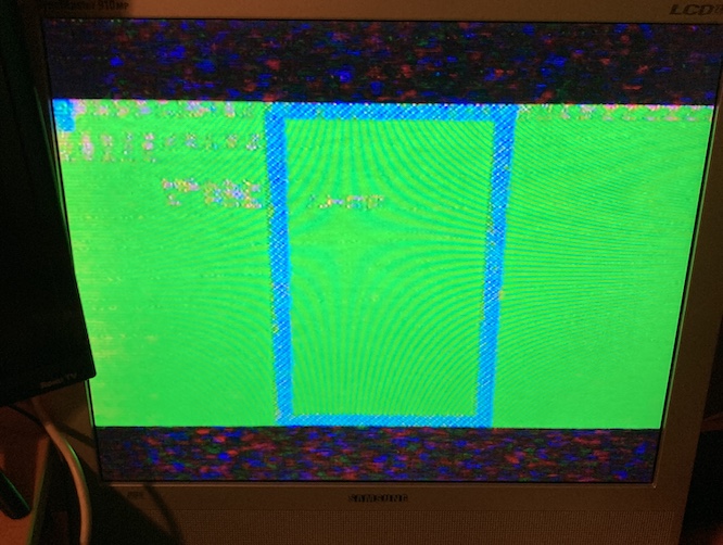
Holy crap. It was muddy, it was swimmy, it was glitchy and unreadable, but it was mine.
Even the controls worked! Here’s what it’s supposed to look like, without the “help” of a disintegrating RF output:
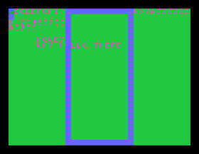
Hardly a “game,” but it’s still all my own code and VDP initialization, learned the hard way, and running on the real hardware. What a thrill! Why would anyone do drugs when they could just push one byte at a time to a Z80 I/O port?
The Dumb Cartridge
Because I intended to keep both copies of Bridge Builder intact, I quickly remade the cartridge in KiCad and sent it off for fabrication. I was pleased to find that JLCPCB has a sort of “secret menu,” where they’ll still bevel the edge on your PCBs without also paying thirty bucks for gold fingers.
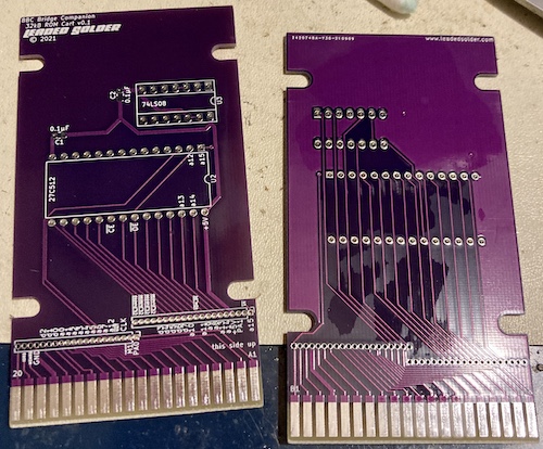
This board was intended to support up to 64kB 27C512 ROMs, although as far as I can tell, no games this large were ever officially released. With just a cheap tin DIP socket installed for the ROM, it’s not great for iteration speed, but most of my development is done in the emulator anyway. I figured it was all I’d need for now.
I decided to test out the board, and my freshly repaired cartridge slot. Unfortunately, it didn’t work. The cartridge, that is, not the repair.
When trying to load my test ROM on my new cartridge PCB, all that I got was the “No.” screen, indicating that the BIOS was not able to read the first couple bytes of the cartridge ROM in order to find the entry point. Those bytes are there, since I’m using a known-good ROM, so what’s up?
Where did I screw up?
My first check on the new cartridge PCB was the obvious one: making sure and were getting toggled. got bumped at startup, just before the “No.” screen appeared, so the chip-select signal was getting all the way from the Z80 to the PAL to the 74HC08 to the ROM. is driven by the console, and was getting pulsed periodically. Not the problem.
I verified the pinout using the pin-header breakouts at the bottom of the cartridge PCB, and the Z80, and made sure there were no shorts between adjacent lines. Doing breakouts like this is a real time saver when you run into an ugly situation like this, and I’m extremely glad I do it even though it makes the routing a lot more annoying.
Since the ‘256 has a programming-voltage (Vpp) pin in pin 1 where the PCB supplies A15, I decided to cut that off and ground it out. This was of course a fruitless endeavour, because the erasing voltage of the chip I was using is 14V, and the programming voltage was 12V, and the Companion doesn’t use twelve-volt logic. Nothing changed.
To make absolutely sure that the chip select logic was working, I bypassed the “decoder” by removing the 74HC08 and jumping from the line directly to the output that feeds the pin of the ROM using its empty socket. Doing so would disable paging, but I didn’t need it to read the first handful of bytes at $4000 , which the BIOS checks before deciding to show the “No.” screen.
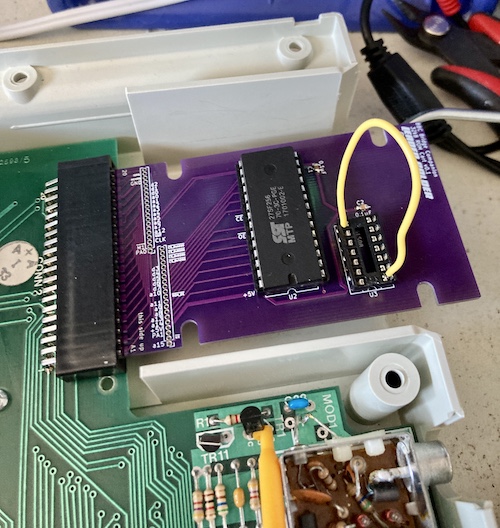
Unfortunately, this jumper job made no difference, and since I had earlier observed a pulse on the ROM’s chip-enable pin as expected, I could reasonably assume that the decoding ‘08 was not at fault. All this check did was rule out that a chip select other than was enabling the ROM.
Even though I was certain that, since it was an active-low signal, the fault wasn’t caused by my use of a 74HC08, I put a brand-new 74LS08 back in, just to reduce the number of differences from the original PCB.
Finally, I decided to just brute force things. If the old PCB worked, and the new PCB doesn’t, there must be some difference that keeps it from doing so. Eventually, I realized that the A14 line was not run on the old PCB to the ROM. Oops.
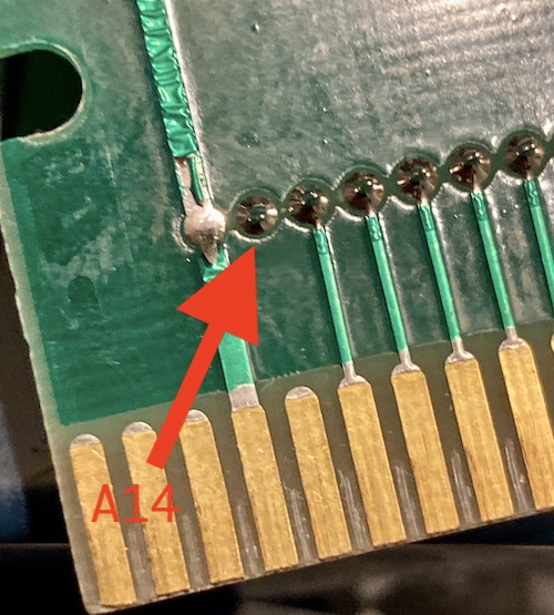
After thinking about it, I realized this made sense. Because the address lines coming into the cartridge are the ones of the CPU, any address delivered to the cartridge is absolute. As such, a read to $4000 (the start of the cartridge in the Companion’s memory map) sets A14 and no other address line.
Since we pass that A14 blindly along to the ROM, it’s like we’re asking the ROM to return the byte at $4000 of itself, when we actually wanted it to return the byte at $0000 .
No wonder it wasn’t working if the ROM was returning some garbage from 16kB into it instead of the actual start of ROM! I cut the A14 line, and now I didn’t get the “No.” screen anymore.
OK – I’d have to figure out a better way of doing decoding if I want the cartridge to actually work with a big ROM, but the colour test program is small enough that I don’t have to worry about page switching for the time being.
It worked, and now I could continue developing my game, knowing that I had a cartridge to put it in.
Repair Summary
| Fault | Remedy | Caveats |
|---|---|---|
| (1987 unit) Cartridge slot is damaged | Replace cartridge slot. | New slot is tighter fit than before, has really poor strain relief. |
-
The manual actually describes what kind of plug you should buy to graft onto the adapter. It was a bit shocking to me as a Canadian that a manufacturer would “trust” a customer with something like DIY power cord construction. After asking Johnny about it, it was explained that some English electronic products were sold through to the mid-80s without a plug due to competing standards and also cost savings. A standard was established in the late 80s, which also seems surprisingly late. ↩
-
Like the NTSC TMS9118 in the PV-7, the PAL TMS9129 only requires two DRAMs for video RAM. The TMS9918/TMS9919/TMS9928/TMS9929 have DRAM refresh and indexing logic for eight. ↩
-
Porchy on BlueSky let me know that they have brute-forced and dumped the BBC Bridge Companion’s PAL at IC1. Thank you Porchy! If anyone is feeling ambitious, it should be pretty easy to make your own clone Bridge Companion at home now. ↩
-
I’ve told this story before, but the previous owner told me, after taking the $10 cash I paid for it, that he thought it got hit by lightning. ↩