In Need of Adult Supervision
Tags: console watara supervision corrosion repair
If you read a lot of gaming magazines in the early 90s, you might remember being confused about some crude ads for this handheld game system. For everyone else, there’s a pretty decent repair in this one.
One of the magazines that seems to follow me from place to place, despite the odds, is an issue of Electronic Gaming Monthly (#38) that proudly proclaims the “1992 Fall Preview!” with Ren and Stimpy on the cover. I read this specific issue a lot when it was new. There’s an ad for a Gamate inside, which was a Chinese portable system that enjoyed virtually zero success. It’s hard to find one now, though I still hold out some hope.
What does this have to do with the Watara Supervision? Not a whole lot, other than that the Supervision was also mentioned in a different magazine around then, and I mentally conflated the two along with the Mega Duck into being the same system. They’re not, even though the whole wave of machines seems to have originated from Taiwanese or HK electronics firms at the same time to try and undercut the Nintendo juggernaut.
The Watara product has little else in common with the Gamate, besides the fact that both of them seem to have 6502-adjacent CPUs and a 4-colour monochrome LCD. When I saw this broken Supervision up for sale on eBay, I jumped on it even though the ad came with the dreaded mark of the Global Shipping Program.
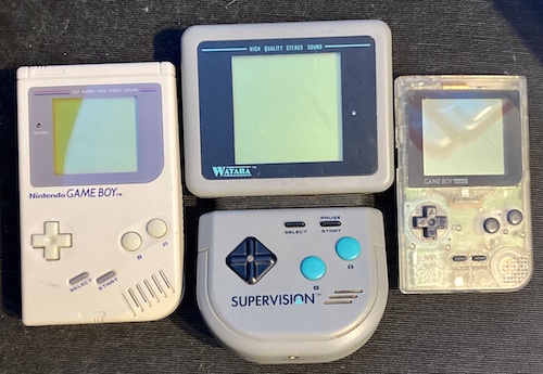
The first thing I noticed upon its arrival, because I’d never seen one of these in person, is that it’s super big. It’s bigger than even an original Game Boy, and I would describe the screen as “generous.”
Here’s a DMG Game Boy, the Supervision, and a Game Boy Pocket for size comparison.
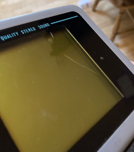
On top of the reported “not-working,” the Supervision also came with this deep scratch in the screen, likely produced by a box cutter opening a package too zealously. At first, I wanted to blame the Global Shipping Program, as that’s the kind of thing they like to do, but then I saw that it was also present (but faint) on the original ad’s pictures.
The entire console is pretty dirty, including the rubber flexy bit in the middle. Also, one of the flip-out pegs for playing the machine on a desk is missing entirely. Clearly it’s had a rough life.
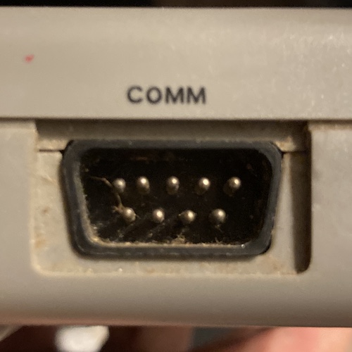
One of the pins in the DE9 COMM connector is bent. The 6V DC (centre-negative) power jack appears to have some blue-green copper corrosion on it, which probably doesn’t mean great things for the power. To make matters worse, the barrel jack is an annoying size - I had to dig around in my junk bin for awhile to come up with one in an orphaned-from-the-transformer universal power adapter kit.
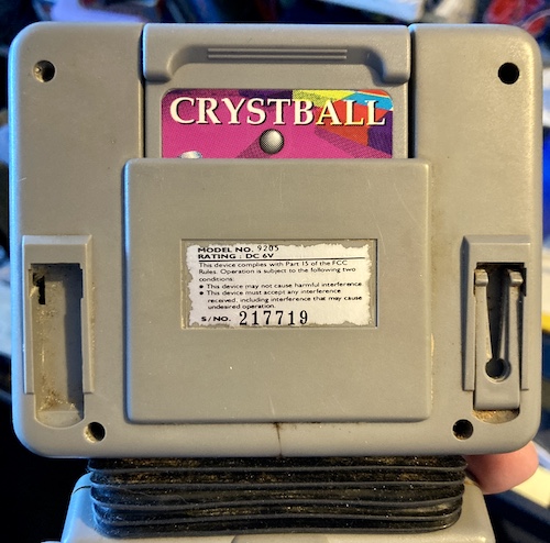
A game awkwardly named Crystball was included, which is good because the Supervision reportedly won’t start up without a game inserted.
The battery contacts are still shiny, which was another huge plus for my chances at fixing the Watara.
Quick Test
To make sure that the eBay seller wasn’t lying about it being broken, I slammed in some “AA” batteries, installed the Crystball game – as stated before, a game is mandatory for powering up the Watara, and the cartridge pins even reportedly complete part of the power supply circuit – and flipped the flimsy power switch to “ON.”
Of course, it didn’t actually work. I didn’t see the screen do anything, hear sound, or see the power light turn on. I tried a few different orientations of the screen, wiggled the switch to check for dead or corroded contacts (Game Boy Pocket style) and tried holding the entire unit upside down while cursing its manufacturer. I also cleaned the cartridge pins and the slot.
None of these simple fixes brought it back to life, so it’s surgery time.
Open It! Open It!
After I left the machine in an airtight bag for a few days to make sure nothing was alive inside, it was time to figure out what’s wrong.
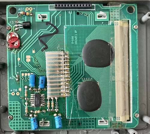
It’s not hard to open it, just a little fiddly, but wires are soldered to both of the back plastics. And hoo boy, is the soldering ever bad. Just take a look:
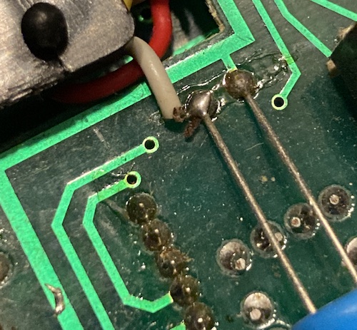
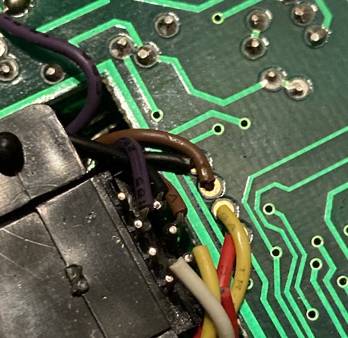
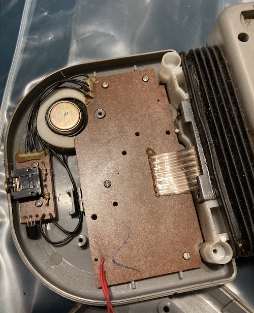
I don’t pretend to actually be good at soldering, but this was clearly put together in a hurry. Cold joints, underfilled pads, and lots of other little assembly problems let down what appears to be actually a fairly high quality (is that actual gold plating?) set of PCBs.
Even so, no obviously severed wire was dangling around loose in the case, so whoever put this together still did a good enough job to last nearly three decades. They’re also a pretty big jerk for using red wire for both battery positive and negative.
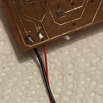
It bothered me so much that I immediately fixed the problem, with some black stranded wire I had on hand. It’s also a little beefier, so maybe it will help prevent ground bounce through some unlikely form of magic.
I wasn’t happy about the hot glue shoved onto the ribbon cable that connects the two “halves” of the machine, as the ribbon cable looked like it had taken a bit of a kink over the years and is now stiff and possibly not continuous – a prime suspect, as it is used to carry the juice from the batteries to the “rest” of the machine. In order to probe this “spinal cord” for continuity, I had to remove all of the boards from the case, which meant dealing with the extremely gross (and sticky) rubber bellows, as well.
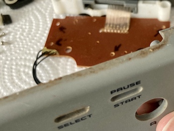
Everything about these plastics were gross. The missing “foot” on the back let in even more gunk, which settled behind the contrast dial.
Once the case plastics were removed, I could wiggle the rubber bellows off. Something on it was very sticky (probably glue) and gave me a slight contact rash on the inside of my wrist. When I washed the rubber bellows in the sink and scrubbed off all the Mother Nature with a toothbrush, it turned the water first dark grey and then yellow. Yuck!
It was still extremely sticky afterward - I probably transferred some of the glue from the inside to the outside during the removal process. After studying up on different kinds of rubber, I determined it was probably EPDE, which is safe to use acetone on. Even so, I was extremely nervous about it and started in a small corner where hopefully any melty rubber wouldn’t be seen. To make matters worse, I was working with a single nail-polish-remover pad whose package looked like it was from at least a decade ago! I’ve definitely restocked my acetone supply since.
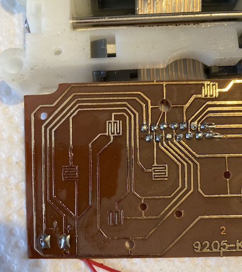
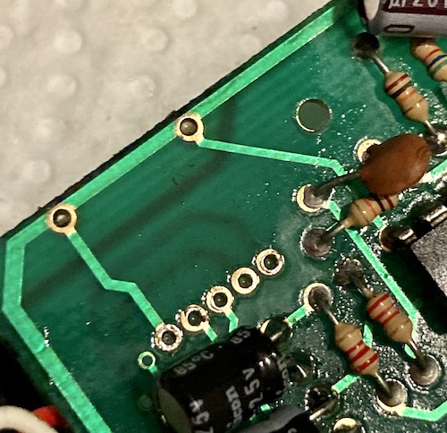
The bottom board is kind of interesting - instead of silkscreen, they’ve got the positive and negative battery terminals as part of the trace drawing. I gave it a quick cleaning with isopropyl alcohol to make sure the pads were clean. It would stink to get it working again and then have to tear it all down just to fix a spotty A-button.
I buzzed out the ribbon cable - continuous on every pin. Ah, that would have been too easy. Same with the power switch, which gives a clean beep as it moves from position to position.
I split the LCD board from the motherboard. My reasoning was that the power jack and power regulation is on the motherboard, nothing obvious was wrong with the LCD board that I could tell, and if anything was hugely wrong with the LCD sub-system, the machine was probably a brick anyway. Better to start out by sticking to the part of the machine that doesn’t scare me as much as an 80s LCD.
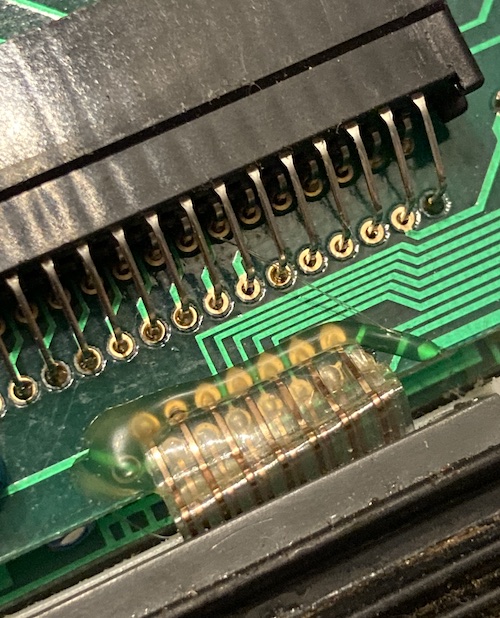
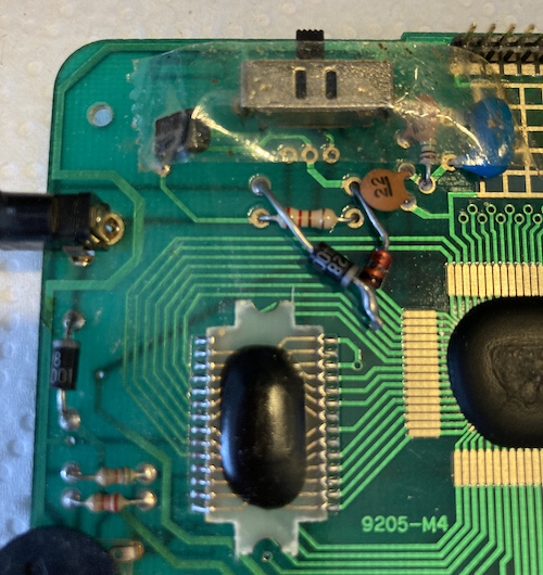
There’s no traditional “packaged” ICs on the motherboard, just these glob tops with fibreglass carriers. I hoped these weren’t the problem, and pushed on. No silkscreen here, either, if you’re keeping score.
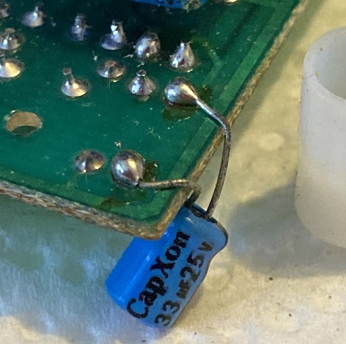
The caps seemed to be made by CapXon, which later on would become infamous for being one of the main culprits of the “capacitor plague” that helped to make preventative re-capping a thing.
CapXon caps have knocked out a ton of TVs and LCD monitors, but I don’t think they’re the culprit here. A cap would be more intermittent, whereas this “feels like” a broken circuit somewhere.
I did a bunch of preventative re-flow to clean up anything that looked like a bad fillet or a broken joint. It was probably largely pointless as the plated through-holes seemed to be in good condition with no corrosion. While I was looking over the board, I chucked the buttons in the ultrasonic cleaner to work the built-up ridge of human slime off of them. Everything came out alright, except that the d-pad has some wear to the plastic from rubbing up against the shell over time. Nothing unusual.
Clean It. If It Still Doesn’t Work, Clean It Again
I took the plastics apart as much as I could and started washing them in the kitchen sink, including the battery compartment and screen lens holder. I was worried about the label on the back half, but it seems to have held up alright. A lot of grit came out of the grooves in the case when I scrubbed with a toothbrush, and eventually things finally seemed to be going in the right direction.
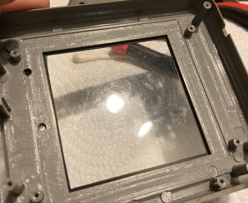
Originally, I intended to try and polish up the screen lens with Novus plastic polish to make the machine look spiffier, if not take out the big scratch in it. Unfortunately, the scratch went all the way through the plastic, so I didn’t bother. Thankfully, it didn’t seem to have touched the LCD glass. Someone should make a new screen lens.
Normally, I would use some 303 Aerospace Protectant on the plastics after washing them. The stuff is really magic on dashboards, console bodies, and convertible tops; it helps to revive and protect them a bit. In this case, I don’t like how greasy it makes hand-contact surfaces (like the entire console) and I also ran out of the magic goo a few months ago, and apparently without the ability to get more.
Speaker Beaker
Unfortunately, when I took apart the front panel, I found out that the speaker was just as bad as the rest of it. It seems like this was in water for a little while, because the metal grille of the speaker was rotten and had even dropped chunks of gritty black metal inside the holder.
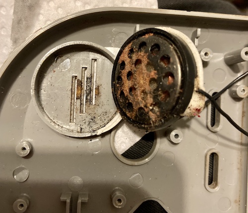
Those of you who paid particular attention to the earlier photos may now be asking yourself how it is that this console can have “high-quality stereo sound” with only one speaker. Hey, I just work here, alright?
Although the wiring inside that grille looked to be the right colour, I figured it would be straightforward and cheap to replace the entire shebang with new. Finding a replacement speaker is not something I’d done before (you may recall that my Game Boy Macro is still very much a mute,) but I figured I would at least give it a try.
The diameter of the speaker was 26.7mm and the resistance across its terminals was 33.6Ω. It said “P” on the back of the yoke cover, so all in all I had nothing good to go off of. I moved on with the repair.
New Jack City
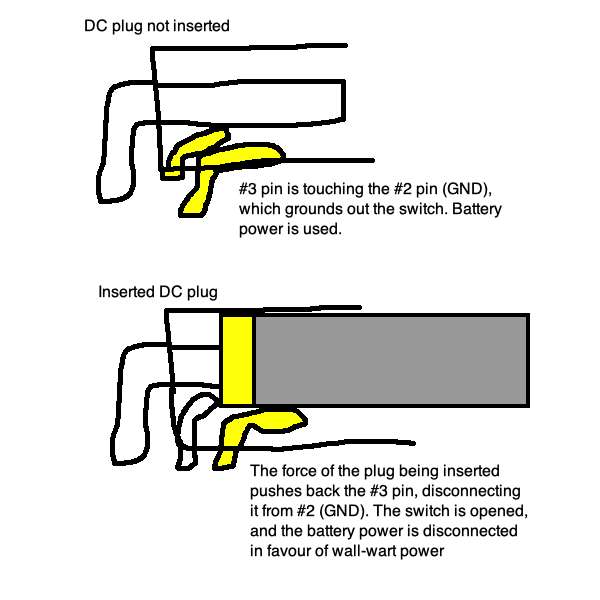
Eventually, after a lot of thinking and poking around the boards, I came back to the DC jack. Like with the Sega Nomad, the DC jack in the Watara will “switch” the battery on and off when a DC plug is inserted into it. It does so by severing the connection from the positive terminal of the battery pack and substituting the positive “sleeve” of the DC jack in its stead.
Here’s the crappy diagram I drew when I was repairing the power jack on the Nomad, in case you’re one of those visual learning types:
I remembered that during the visual inspection, I thought the jack looked fairly corroded, and decided to test in-circuit.
It failed a few critical tests:
- No continuity from centre pin to any of the three “solder side” pins on the jack;
- No continuity from the sleeve leaf to those either;
- The side “switched” pin (battery positive, via a diode) was not continuous to either of the other pins on the jack, indicating the switch was open and the batteries were disconnected from the power system;
- Jamming a plug into the jack didn’t fully seat, because something was holding it up from going in.
I then desoldered the jack, and did all these tests again with the jack removed from the system. They all failed identically.
Once the jack was out, it was now extremely easy to see what the problem is. This thing is rusted shut, and not in the way that would be beneficial to us (where the “positive” sleeve is rusted to the “switched” pin internally.) I wonder if a bug or something made its nest in here?
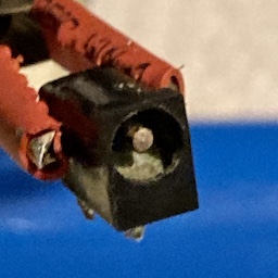
A couple minutes in a vinegar bath produced a torrent of angry bubbles, but no change in behaviour. Time to get a new jack. They’re cheap…
I bought a 98¢ CUI PJ-013D barrel jack (1.30x3.40mm) to replace the original part. Although it looked like the connector-designing engineers had made some reliability improvements over time to the centre pin and some strengthening ribs, the important dimensions of the plastic case were exactly identical to the old part, and the jack-insertion switch mechanism worked the way I originally expected it to. It was a quick job to solder it in.
Recap Everything All The Time
I figured that because taking this thing apart is so time-consuming, I might as well also do some more preventative maintenance while I’m in here. Plus, I already had the parts on hand, and even the crappiest caps in my bin are probably still better than thirty-plus-year-old 85°C electrolytics… and my personal, likely undeserved, bias against CapXon.
Here’s the table of values, anyway: all common values, and not a lot of different ones, showing some good cost engineering at work here.
I suspect because of the wide variance of Supervisions, yours is likely to have different values, positions, sizes, and caps than mine. This listing is for entertainment value only, I guess?
Motherboard Caps
Note that because of the lack of silkscreen, there are no real “position” callouts on these caps. So instead, you get some vague description of their positions.
| Capacitance (µF) | Voltage (V) | Vague location |
|---|---|---|
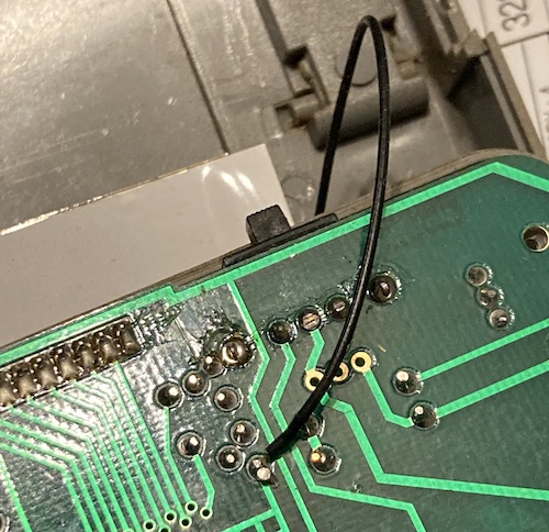
| 220µF | 16V | The cap with super long legs (comm port decoupling?) |
| 33µF | 25V | Stubby one near the cart slot |
| 33µF | 25V | The other stubby one near the cart slot |
| 33µF | 25V | The dangly one on the edge |
| 33µF | 25V | One of the pair near the LM358N |
| 33µF | 25V | The other one of the pair near the LM358N |
| 4.7µF | 50V | Small cap near 74HC14, DE9 port |
| 10µF | 25V | One of the triplet near the board-board connector |
| 10µF | 25V | One of the triplet near the board-board connector |
| 10µF | 25V | One of the triplet near the board-board connector |
Unfortunately, when I first tried this, I quickly found that practically all of these caps need to be identical to their original sizes. As a result, I did not complete a full recap at first (more on this later,) because the caps I had on hand were so tall that the case would not be able to close with them installed. If you’re going to set on this quest, please do a better job than I did measuring for the replacements.
The 33µF caps are about 7.6mm tall and 4.3mm wide. Apparently these are difficult sizes to hit nowadays at these voltages if you’re buying quality caps from a reputable distributor, so I made some slight adjustments on my second order and let the diameter go up to 5mm and the height up to 8mm.
LCD board caps
I’m not sure I can actually recommend doing these. Taking this board sandwich apart is sketchy, and you’re more likely to damage something than you are to make things better.
They’re identical values, so no position information is needed.
| Capacitance (µF) | Voltage (V) |
|---|---|
| 4.7µF | 50V |
| 4.7µF | 50V |
| 4.7µF | 50V |
| 4.7µF | 50V |
Startup Test
Because I was still trying to figure out a way to make the rubber bellows less sticky, I couldn’t fully reassemble the machine for the test. In order to avoid losing momentum, I slapped together what I could and fired it up with an adjustable power brick - the same RCA-branded ones I use to run my power supply load tester.
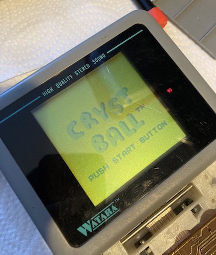
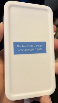
It started right up! Unfortunately, that’s when I realized I had the power brick set to 12V instead of 6V.. obviously their regulation circuit, while seemingly cheap, is pretty good! That’s how I ended up with this note on my AC adapter for future use:
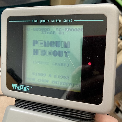
One weird thing is that when starting the console, the boot screen for Crystball doesn’t read “SUPER VISION” as I’d expected from YouTube videos, but instead “TRAVELL MATE.” Apparently Travellmate was yet another publisher for Supervision games?
In order to isolate any other problems during the first test run, I didn’t bother to solder the speaker back in, or hook up any of the buttons1, so this was an incomplete test, but I was feeling pretty good about having repaired this. Well, until I tried hooking up the sound.
It Goes to Eleven (Or Else You Can’t Hear It)
The rubber bellows was still so sticky that I decided to put off the re-assembly of the machine for a bit. While I was waiting, I figured it was best that I do some further testing, including looking at the audio. Because I had desoldered the speaker with the full intention of replacing it, was hook up the headphones to some stereo speakers. After all, if the console truly had the “high quality stereo sound” advertised by the screen lens surround, I’d need all the support I could for the Supervision’s unparalleled aural landscape of CPU-generated three-channel chiptune music.
Of course, I got nothing. I went on to hook up the speaker, and at maximum volume I could just barely hear a chirpy song being played that was drowned out by noise. Could it just be a trash speaker? Going back to the headphones, I discovered that the headphones indeed turned off the speaker (unfortunately leaving some staticky noise playing out of it) and you could just barely hear the game music when the volume of the speakers was turned to near-maximum. We got ourselves an amplification problem. Yee-haw!
No amplifier? How could this be? That STMicro LM358 is built by a name brand.
Because I had them on hand in anticipation of completing the Game Boy Macro project, I also tried a DS Lite speaker. This seemed to make absolutely no perceptible sound (or noise) even at maximum volume, maybe because of differing impedance.
After tracing out the circuit to the LM358, I found out that both the inputs and the outputs travelled through the exact teeny-tiny 33µF/25V CapXon capacitors I hadn’t replaced. I hate it when I’m right… or was I?
After taking some measurements and making a very careful DigiKey order, I had a grip of the correct (or at least closer) electrolytic capacitors in hand. I unwound some of my earlier work so I could get at the joints, and then replaced all the remaining 33µF capacitors on the motherboard. I didn’t bother doing an ESR test on the removed caps, as I had already bought the new ones2. Firing the console up with the speaker soldered in, I hoped to get some sound… and I did not.
Frustrated, I tried poking the board while it was running. Nothing really happened for the first ten minutes or so, so I kept poking. Eventually, I tried wiggling the volume pot out of frustration while it was working, and got a static pop and a semi-loud note of music! Unfortunately, the music quickly faded away on its own.
After spraying some snake oil Deoxit into the top and sides of the volume pot, I was able to get more positions working on the pot (and even more once I let it sit for a day to work - thanks Bell Tone Synth Works for letting me know to be patient), but they too would quickly and smoothly fade away on their own. I’m curious what this was; my best guess is that the low current flowing through that part of the wiper would slowly build up crap from a sort of galvanic corrosion effect and raise the resistance too far for the audio to function any longer.
Time for a new pot, I thought, and started researching. I guess it should not be a surprise that whatever killed the power jack also got into the volume pot that was clogged with mud when I got it. Good thing I have lots of experience replacing volume pots.
Through some kind of miracle (of industrial espionage?) it appears the original Game Boy uses an identical-looking part for its volume pot. Armed with the “B103” designator – indicating a 10kΩ pot – I did an eBay search and found someone willing to sell me ten of these 5-pin miracles for like $3. I put the Supervision aside for a few weeks while I waited for them to arrive, putting all the parts together in a clear plastic container so I could free up my workbench.
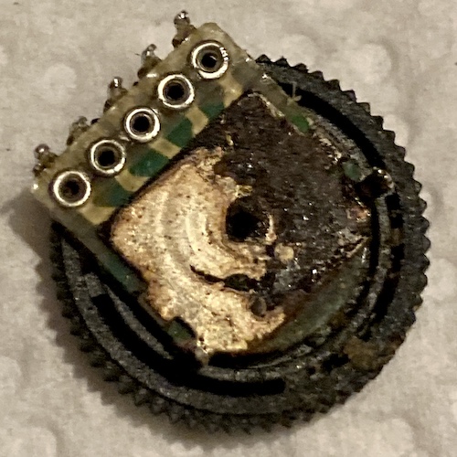
Comfortable in the knowledge that I would be able to replace it, I set about removing the old pot. It was tricky to desolder; the front two prongs, which go to the “ground,” were difficult to fully clear due to corrosion having made the metal swell up. I also noticed later3 the “dial” on the pot was crooked; it seems the corrosion has damaged the construction so badly that it wobbles off-axis.
I had to use a screwdriver to pry the pot off the board, because I originally thought it was glued down… but actually was rusted on! Luckily, the pads and the rest of the PCB looked fine after a cleaning. Whoever made these boards for QuickShot/Watara were absolute heroes. I wish the X68000 PCBs had been this tough.
Once the pots arrived (I got impatient and ordered a much more expensive assortment from Amazon), I popped the 5-pin 10kΩ pot into it. The new component fit like a glove, with identical diameter and pin spacing to the old part, although the new dial was only about half as “tall” as before. Not a big price to pay for having a working volume control again. Notice that the old volume pot did not specify a value, but I figured if it was good enough for the Game Boy, it’s good enough for this.
After popping in the new 10k pot, I noticed that it felt a lot stiffer than the original part. Between this and the wear on the d-pad, someone must have played this little console a lot. Hopefully it all wasn’t just Crystball.
I powered it on with the DC brick and hooked up to the test speakers, and… glorious music!
No good deed goes unpunished, of course, because when the mystery-meat internal speaker was soldered back in, it sounded pretty terrible. You could still make out the sound, and it got pretty loud, but there was also an ugly static hiss and the instruments sounded tinnier, more like a musical greeting card than the nicer quality coming out of the headphone jack. I’m not sure how much of this is from foreign-body or corrosion damage, and how much is just being a crappy speaker. At least it’s easy to open the bottom half of the machine, and replace the speaker in the future.
Putting It Back Together
This was the part that I was dreading most. With no surface-mount parts and some oversized components, a lot of components had just been folded over in a very precise way at the factory in order to clear the case plastics. If it weren’t for the chips being proprietary epoxy blobs, it would have been extremely tempting to redo the motherboard with tiny surface-mount bits for some future project.
Pulling the rubber grommet back on was still gross. After cleaning it with nail polish remover, in the intervening days it had become sticky again on the inside, where I assume the original assemblers had used glue. It looks like I have actually put the boot on backwards, as there’s a wrinkly “lip” on the front now that I think used to be on the backside. It’s ugly, but won’t affect functionality.
One interesting problem is that somewhere along the line when reassembling the top case and testing as I went, I lost video. In a mini-panic, I went back over my old work, and found that a transistor had been bent in such a way that the transistor’s plastic body touched the teeth on the contrast dial, forcing the dial upward ever so slightly so it apparently didn’t make good internal contact. After adjusting it, the screen came back to life, but it was more than a little bit scary.
The 270µF cap that I initially used to replace the 220µF bypass cap with was too big, so it wasn’t letting the rear shell of the display half sit flush. You really need a cap that’s no wider in diameter than the cartridge slot is deep, and you need it to lie flat-flat. I measured the voltage at the cap while the system was on, and found that it was only about 5V. I’m guessing they only specified a 16V part here because it was cheaper to get (related to the TV out?) so I replaced it with a 220µF/10V cap that was much smaller. Once again, the Medusa of wiring around the Comm port was a source of frustration.
The rest of the reassembly went fine, if slowly. Once I got it fully reassembled, I tried starting the console and… no video again! Eventually, I determine that it only happened if the screws were too tight on the back, so I loosened and re-torqued them to be a little gentler. That seemed to do the trick.
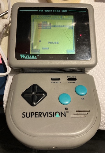
One lasting artifact, and I’m not sure if all Supervisions have this problem, is that the “down” and “start” keys tend to double-register. There’s probably some work I can do here if I wanted to re-open this machine any time soon. However, I was able to rack up a pretty good Crystball score, which is tricky because the slow refresh rate of the LCD makes it hard to track the exact angle of the ball and the paddles. I’ll need to practice more, so it’s perhaps good that it’s the only game I own for this machine.
I tried a few times to get a good angle (I even bought a cheapo smartphone tripod!) for this video of the Crystball attract mode.
After some late-night frustration trying to get the smartphone aimed at the entire console in an interesting way on my limited workbench space and crappy lighting, I ended up filming this other video by hand in shakycam mode:
Despite the fact it’s plugged in on both videos, the console also worked great on AA batteries.
I’ve pretty much only been playing in the “sitting up” orientation, because putting it in the flat “Game Boy” orientation makes the heavy screen sag backwards. It’s disconcerting to see it bobbing around. With only one foot, it’s hard to prop the system up on a table as well, so I’ve been sticking a PB Blaster lid behind it to keep it up for the video.
Bonus Content: Penguins!
I’m not going to lie to you: I got bored of Crystball pretty quickly. I also wanted to get a game that would let me test more of the controls, to make sure I put this thing back together again. A French eBay seller was willing to play the offer/counteroffer dance with me, and so I ended up with a gently loved copy of Penguin Hideout.
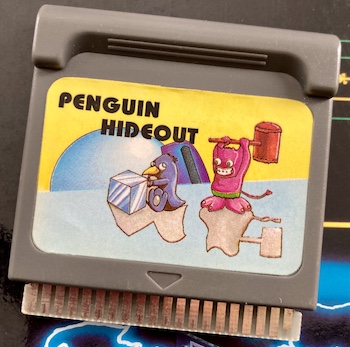
One weird thing I immediately noticed when it got here is that the cartridge plastic is not even remotely the same shade of grey. Perhaps they used a different colour, or it came from another brand’s Supervision-alike.
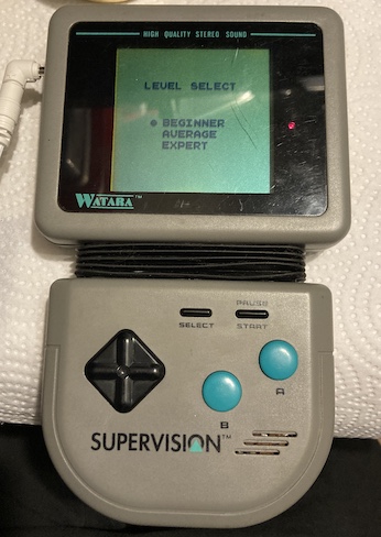
After some cleaning of the cartridge pins, it started right up. I found this game kind of hard; it’s sort of like a Boulderdash-alike where you have to blow up some clods of dirt and extract diamonds hidden in the level. There are some respawning bad guys who are hard to track because of the motion-blurry LCD, and I kept getting my penguin butt kicked.
With some practice, I got a little bit better at it, but Penguin Hideout is unlikely to get into my lifetime top-10 list of favourite games.
Conclusion
Bringing this gross Supervision back was a labour of… I wouldn’t say love, but definitely stubbornness bordering on an actively hostile grudge at times. Still, it’s a neat piece of history, and it was probably destined for the trash bin otherwise. I don’t know how many other folks would have bothered saving it.
There’s still stuff to do: the huge gouge in the screen lens, the missing foot, the touchy controls, the dodgy speaker, the saggy hinge, and the unsightly rubber boot in the middle.

Well, that’s interesting.
Repair Summary
| Fault | Remedy | Caveats |
|---|---|---|
| Screen lens has a deep cut in it. | Not fixed at this time. | |
| Dirty. | Significant washing. | Risky to clean/disassemble the LCD housing. |
| Bellows was unusually sticky from glue. | Clean with nail polish remover pad. | Not all rubber is acetone-safe. Still kind of sticky, so not all glue was removed. |
| DC power plug didn’t go in | Replaced corroded DC jack with PJ-013D | |
| Did not power up on batteries | Replaced corroded DC jack with PJ-013D | |
| Speaker badly corroded | Not resolved at this time | Speaker sounds really bad |
| Faint, buzzy audio on both headphones and internal speaker. | Replace volume dial with new 10k pot | 10k might not have been the original value as speaker sounds like trash and becomes quiet before the dial is at zero |
-
The lack of PCB silkscreen also extends to capacitor polarity markings, which meant that when I took a capacitor out, I had to put another back in pretty quickly, unless I wanted to squint at my old pictures to try and figure out which side used to be negative. ↩
-
Blog friend Grant, previously of modified IBM Model M fame, gave me three dollars to lick the rusted pot. I’m not ashamed to mention that only at this point did I notice this particular aspect of the damage. Said three dollars has since been recycled into a different Chinese handheld console (spoilers!) ↩