That name again is Mr.PC
Tags: computer nec pc60 mr-pc pc6601sr pickups corrosion batteries repair floppy capacitors gotek homemade-software
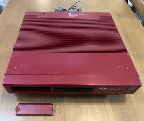
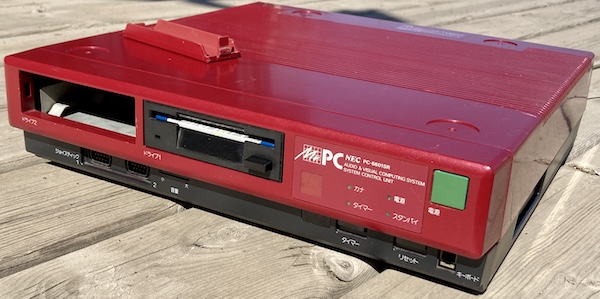
Get ready to step into the cyberpunk future of the mid-late 1980s, and don’t forget to bring your boxed wine. NEC pulled out all the stops on this, their final PC-6001 computer. I have to pull out even more stops to get the disk drive to work.
Because I love my rescued PC-6001 very much, and occasionally stare at the busted-keyboard PC-6001mkII while I consider purchasing a pile of keyswitches in order to service its keyboard, I’ve always been curious about the Mr.PC. It’s the top of the P6 line, it had a couple of very 80s TV commercials, and even MAME and old-computers.com don’t know anything about it, with the latter having only a small post about its predecessor, the PC-6601.
Naturally, I started hunting for one on Japanese auctions, dreaming of what owning this extremely fancy PC-6001 would be like. These things never come up for auction - I think I’ve seen one or two listings since I started picking up Japanese machines - so when I saw this one, I bid way too much. And won.
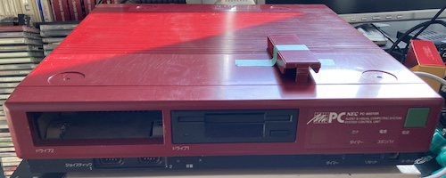
Please pay some special attention to the round recesses in the top of the case, which are presumably meant for securely mounting its companion monitor. In what is almost certainly a response to the Sharp X1, the PC-TV151 monitor also doubled as a computer-controlled television set that was styled to match the computer1. Someone had a really fun day at work designing this thing.
What is a Mr.PC?
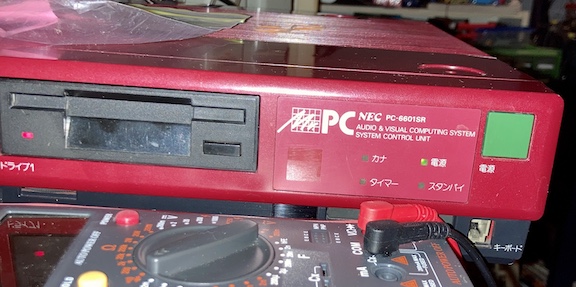
The Mr.PC is NEC’s marketing name for the PC-6601SR – you can also see “PC-6601SR” written on the front of the case. It’s hard to figure out an exact timeline or reasoning for the rename, but the machine was effectively the final PC-6xx1 series machine to be sold by NEC.
I’m not entirely sure if the name is a deliberate reference to the John Coltrane song, but I wouldn’t put it past them.
There’s another nickname for the PC-6601SR - a “Roppongi PC.” I’m not entirely sure why. It might have something to do with one of the ads.
This official commercial for the Mr.PC hits all the cool features you really need to know:
The 6601 series (consisting of the 6601 and 6601SR/Mr.PC) are broadly similar to PC-6001mkIIs, but with a one-sided 40-track (“1D”) 3.5” floppy drive added. The lineup was taken one step further with the Mr.PC/SR, which added a single-sided/80-track (“1DD”) floppy drive, a telopper board with an NTSC composite video genlock, so you can superimpose your computer graphics onto video inputs, like on the X1 Turbo), and it even came with a PCjr-esque wireless keyboard.
Although exact sales numbers and English-language information are hard to find, the rarity of these Mr.PCs implies to me that it wasn’t a huge hit. Presumably, NEC decided they would surrender the bargain-basement of the market to MSX computers while focusing on the more successful PC-88 and PC-98. They did offer the super-budget PC-8801FE a few years later, by 1988.
There are a lot of similarities between this NEC and the Sharp X1 Turbo - another inexpensive consumer-focused machine with TV genlock, a very limited colour palette, floppy drives, “fun” paint colours, FM sound, and a Z80. It’s not a perfect comparison, but the specs line up fairly closely between the two models. They’re even physically about the same size.
However, let’s review the important facts that make it an ideal fit for this blog:
- It’s red;
- It’s the ultimate PC-6001;
- It needs some work.
As I could see from the auction picture, it needed some plastic repair to the “dummy” drive cover, as well as a keyboard. Unfortunately, it’s really hard to get a Mr.PC keyboard. It might be a bit of a blessing in disguise, actually, considering how unreliable the original PC-6001mkII keyboard was.
Arrival
When the machine arrived, I was more than a little blown away by the colour when I pulled it out of the bubble wrap. With the black trim and the glossy red body, it reminded me of the “Iron Mask” 1983-84 Nissan Skyline RS-Turbo, which surely isn’t a coincidence. Said Skyline was popular at the time, so much so that NEC/HAL included the racing game featuring it (Hashire! Skyline) in the PC-8001 Mini release a few years ago2.
I was a little surprised to see a cartridge slot like on the PC-6001, but I guess they must have maintained one even though they had a perfectly good floppy drive. More expansion slots are always good, in my book.
Around back, you have the same ports as on the PC-6001mkII – RGB, cassette, composite output, printer, and a blockoff plate for the missing RS-232 option. There’s also an interesting barrel-jack connector marked “RF Power Out;” I have no idea how that would work (maybe it switches the special monitor on and off?) Like the Sharp X1, there is also a connector for “TV control,” although it’s an 8-pin DIN on the NEC.
The plastics are pretty scratched up, and some of the scratches, like this one on the side of the front panel, are deep. It looks like someone also scratched the hell out of the case trying to pry the floppy drive cover out without removing the front fascia first, and there are a couple deep gouges on the top case as well as storage damage on the corners. All this is a huge shame, considering how beautiful the colour is in the sunlight. It’s even got a bit of metal flake glitter to it, which is hard to capture in pictures.
I’ll have to break out the Novus and see if I can polish them back into their former glory.
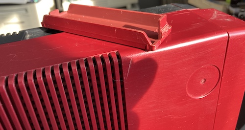
The loose floppy-drive bay cover has a broken tab on one side. I tried popping it back in myself, and it just fell inside the computer. I decided not to fix this yet; I might be one of the few 66SR owners to end up with dual floppy drives anyway.
Time to dismantle the machine. I started by removing all the screws on the bottom, which let the front cover pop off, and then you can pull the top case straight up.
One thing that stinks about the construction of this machine is that the top case holds onto the floppy drive, so in order to take it apart, you have to balance a heavy top case in one hand while unplugging all of the cables that still connect it to the motherboard with the other. The cables aren’t long enough to set it aside.
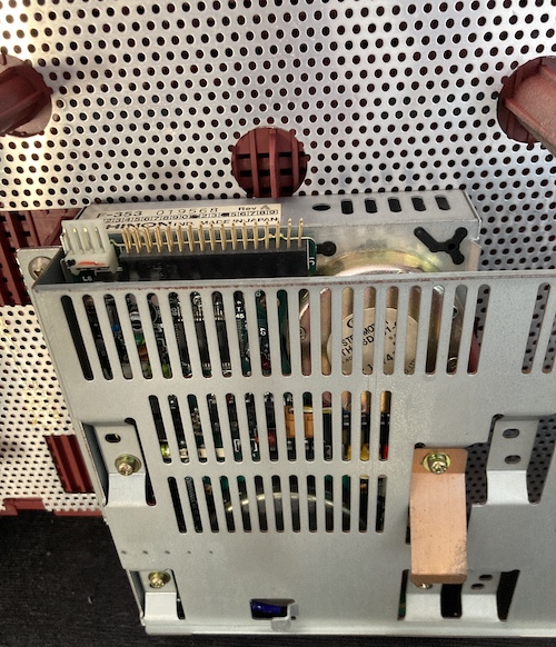
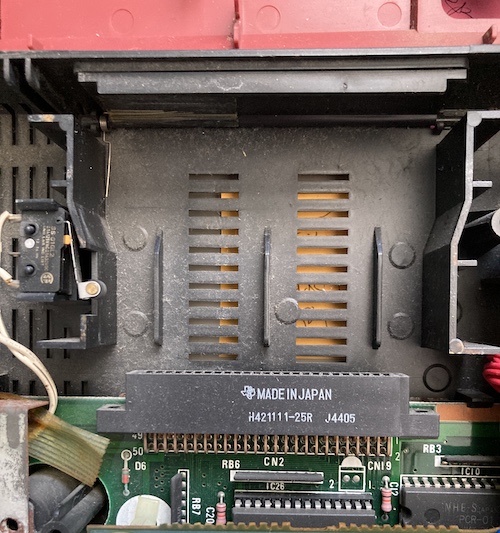
Eventually the Chinon F-353 floppy drive is exposed, on which I can find little information other than that it was also used in an Acorn Electron Plus 3 and inside the uncommon SF354 single-sided external disk drive for the Atari 520ST. The drive connector is not keyed, so remember the tab on the floppy drive cable points up.
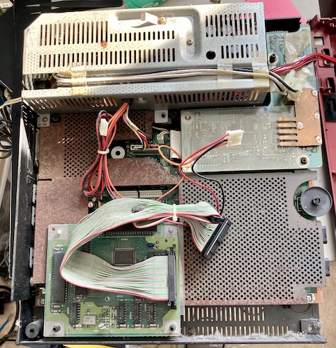
I was a little disappointed to see all this rust on the RF shield of the motherboard. It’s not just surface, either; big chunks of the bottom shield were flaking off and even cutting into the plastic. You can just dimly see the connectors which will add an RS232 card to this computer. That’s right, NEC didn’t throw in a serial port on this one either!

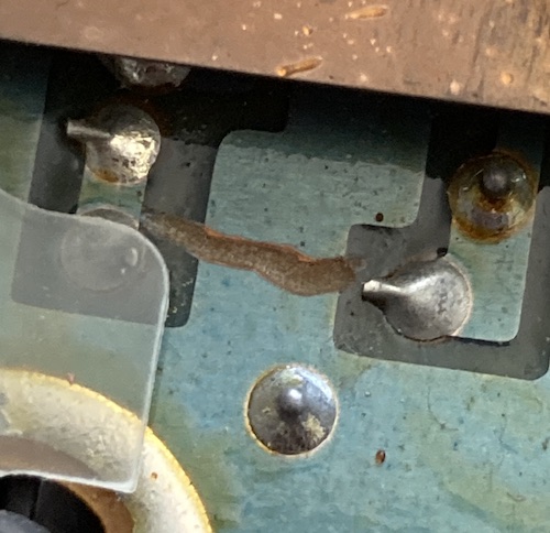
This weird black thing was stuck to the floppy cable. I don’t know if it was some kind of sticky pad that has disintegrated, but I threw it out along with all the other dead bugs and gunk inside the machine. Both floppy drives mount onto the same cable, and the secondary drive connector was ziptied over itself, which told me that this computer has never had dual floppies in its life.
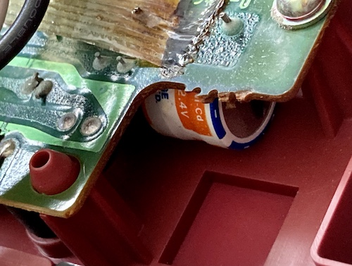
That’s when I saw it. On the front panel, the telltale sign of a barrel battery. Oh no!
Yep, it’s the same brand of battery that did so much damage to my X68000 ACE. Bad news! I don’t think it’s a good sign when diodes have green corrosion inside them, is it?
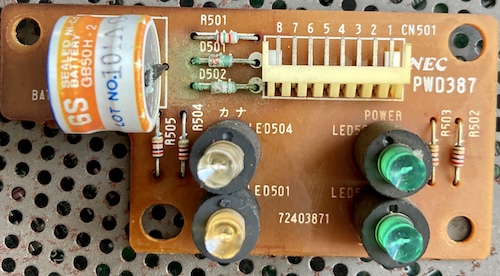
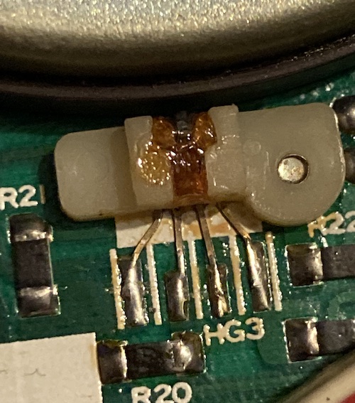
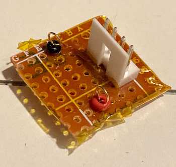
Don’t get me wrong: I’m really glad that the designers of this computer put the clock battery somewhere far, far away from the motherboard. However, it would have been nicer still if they hadn’t put it near this hard-to-find right-angle connector. This PCB mounts into the front panel and provides the LEDs for power/kana/keyboard input/etc.
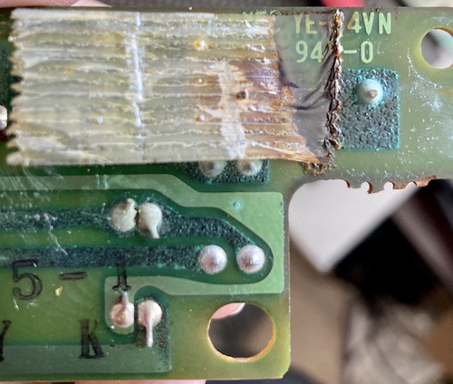
Check out how this cellophane tape melted under the battery leakage. Chemistry is fascinating!
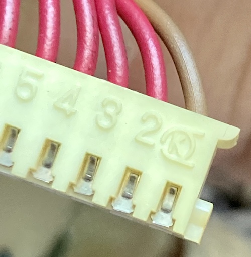
The mating female connector for this LED board seems to be in surprisingly good condition, outside of some uneven yellowing. I don’t know what this logo is, but I’m glad I don’t have to try and find a replacement male connector for this.
I did a little bit of solder-mask removal, joint cleanup, and tracing-out, and it seemed to be mostly okay. I replaced the diodes with 1n4148s, but they will likely never get used as I didn’t replace the battery, and so no current will flow through them. Any battery replacement would have to be done with another barrel battery or routed to an external holder, because unfortunately the footprint and the board size is too small to fit a 20mm (i.e. CR2032) coin-cell socket.
I didn’t want to spend the effort and expense to rebuild such a precisely measured board (LEDs, connectors, screw holes) if the original was good enough for now. I threw some parts together, bench-tested it, and all four LEDs seemed to work the way I expected.
Then I took out my little syringe of solder mask and masked off the exposed copper to protect it in the future. This was a bit of a learning experience since it was my first time using this stuff, and I made a huge mess by using way too much. To make matters worse, the work was being done in the dead of winter, so getting UV exposure was a matter of sticking the board on a windowsill during a sunny day and hoping that enough UV would get through the glass to cure it.
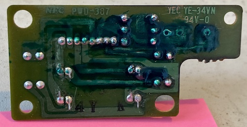
It seems to have worked, but the work is sloppy and looks amateurish. Which, being my first time, is probably a fair assessment.
A more suspicious part of the computer is on the sub-board that holds the infrared keyboard receiver, keyboard port, and a big DIP that I’m guessing is the keyboard controller. This big trace has been severed, and it doesn’t look like it was done accidentally as the cut is very deep.
Because of its proximity and exotic nature, I’m suspicious that a previous owner may have been trying to disable the infrared keyboard receiver as part of a repair – maybe it was shorted and keeping the computer from coming up? The cold solder joint is also extremely suspicious. I guess we’ll find out what happened here when I get around to the “keyboard” part of this project.
The 50-pin cartridge slot still has a “reset” microswitch like on the original PC-6001, so that you can’t go around jamming cartridges in and out while the computer is running. However, on this model, the microswitch is on an easily unpluggable connector. No soldering iron needed to remove the motherboard. Good job, NEC.
I’ve been told the pinout of the cartridge slot on the mkII and onward PC-6001s is not the same as my “original” model, but it’s not clear to me how. Possibly, it is related to the different memory map, and I’ll need to do some research if I want to one day make a cartridge that will work well on both kinds of P6s.
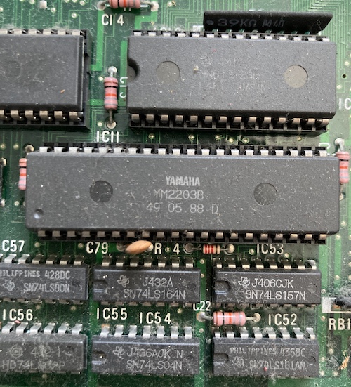
This very dusty Yamaha YM2203 OPN provides the FM sound for the Mr.PC. As a 1988 date code, it indicates that this is probably one of the very last machines produced. I cleaned out some dead spiders and some eggs from this area of the board, as well. Just the usual old-computer interior funk.
While I had the motherboard exposed, I did a couple quick-and-dirty in-circuit continuity tests to see if any of the tantalum capacitors were shorted. They didn’t appear to be, but in-circuit tests can be pretty unreliable, and the caps could die during the initial startup current surge anyway.
Unfortunately, the initial goal of painting those shields was aborted as a cold snap developed and it was too cold in the garage for paint to adhere. For now, they’re not going to get worse in my low-humidity environment as opposed to the brutal weather of Japan, and they can wait for a future job – I’ll definitely need to clean the plastics better as well as try to polish out some of these scuffs.
Test Fire
After reassembling the case, which was a huge pain in the butt to get all the large, floppy plastic parts aligned without puncturing or squishing a cable (turns out all those sticky pads did something after all), I plugged it in to my stepdown transformer and pushed the power button. The power light came on, and the floppy drive clicked and started to spin. And kept spinning.
I took a quick break to figure out my video-out situation. Like the PC-6001mkII, the PC-6601SR/Mr.PC uses an 8-pin DIN carrying digital RGB+Intensity data. Luckily, the R, G, B, and sync pins are in exactly the same places as on the video cable I built for the PC-8801mkII all those years ago, although the PC88 didn’t have the “intensity” pin. I’d be limited to 8 colours (23 = 8) instead of 16, at least until I built some colour-decode logic for it and my PC-6001mkII, but at least I’d be able to see something. And see something I did:
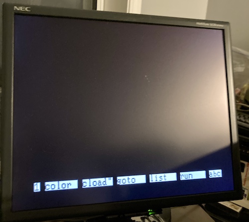
The computer was frozen during boot, and I assumed it was waiting on the disk drive to return from its long vacation doing whatever it was doing. But! Video. This is a success in and of itself.
When I first got the computer, I noticed that the floppy drive’s ribbon-cable connector was not keyed. Usually there’s at least some indication on the drive of which way the tab on the cable points, and if not, you can puzzle it out from the red stripe on pin 1. In this case, the cable’s tab was facing “up,” which meant that pin 1 was closest to the power connector of the drive.
Because the floppy drive was acting like a PC floppy drive does when you put the cable in upside-down, I immediately assumed I must have put the cable in upside-down and so took the computer apart again to flip the cable. This time, reassembly was faster, but the behaviour was exactly the same.
After trying to find some YouTube videos of the computer starting up, and asking a knowledgable Japanese fan, Hashi6001, on Twitter with the “help” of Google Translate, I got the impression that this behaviour was probably not normal. Although the boot is slow with no floppy disk inserted, the computer should only wait on this screen for about five seconds before giving up on a disk boot.
I put a sacrificial 3.5” disk into the floppy drive to test. The behaviour didn’t change, with the spindle motor running forever, and to make matters worse, the disk didn’t fully eject - it only popped up on the spring carrier but wasn’t pushed out by the little pushy-arm thing in front of the diskette.
After pulling the floppy drive out and buzzing out the pins to figure out which ones were ground and therefore odd-numbered, I determined that the original “tab-up” orientation was the correct one, which should come as no surprise as that’s the side the “sticky” bit that I cleaned off was clinging to.
To isolate the problem, I unplugged the floppy drive from both the power and data cables and attempted to boot, where I was rewarded with this screen after a few seconds of loading:
They should have sent a poet.
It’s a Flop
Is the floppy drive the problem? I plugged the drive back in to just power, and the drive stayed silent, with the access LED lit up very dimly. When the reset button on the computer was held down, the drive immediately stopped spinning. I assume this is because the floppy drive controller is being held in reset and is no longer asking the drive to run its spindle motor.
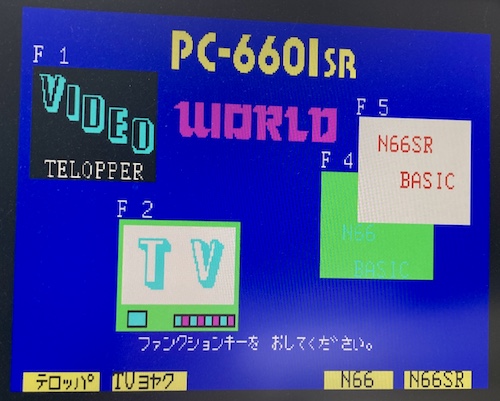
Hashi6001 told me to look at the back of the computer again, where there is a DIP switch for 0, 1, or 2 disk drives. Because there is no way to automatically detect the presence of a Shugart disk drive, when you wanted to install a second floppy drive, the DIP would be set to “2.” I set it to 0 in order to test, and the computer booted to the “PC-6601SR WORLD” menu, but the disk drive was still constantly running the spindle motor, although the LED on the front was now dim.
This combination of phenomena made me suspicious it was a problem somewhere in the drive logic or sensors, rather than a direct mechanical fault like a short.
I pulled the Shugart-configured Gotek out of the X1turbo momentarily to test with, and got to the same “PC-6601SR WORLD” screen after a quick bit of polling the (empty) floppy drive. Later, I also did an additional test with some disk images from the Neo-Kobe collection, and they sorta worked (more on that later.) As well, the +5V rail was showing exactly 5.00V at the floppy drive, which is somewhat impressive. I tried unplugging the floppy controller board entirely, and got an instant boot, without even the short polling for an empty Gotek or missing floppy drive.
With all this in mind, I reasoned that the floppy disk controller and cables were probably “good enough,” and the problem was more likely to be on the drive itself. Let’s inspect the drive!
Driving Miss Fluxy
My theory was that since the spindle motor is running forever, the floppy controller might be looking for an index signal from the drive. If that index sensor were dirty or broken, then it stands to reason that the computer would never stop spinning the drive, eternally waiting for the index to be sensed, so that the drive would be in the right position to read the boot sector of the disk. Because the amount of time that passes since you’ve “seen” the index is effectively the only way for the floppy drive controller to know what the rotation of the disk is and therefore what sector is being read/written, index is super important. To use a car metaphor, it’s akin to running a gas engine without a crank position sensor.
It seemed like a good enough theory to go on, and considering floppy drives get gross over the years, it’s a miracle of engineering that any of them work at all.
I didn’t think it was the “track zero” sensor, because then I’d expect the head shuttle motor to be moving forever and rattling against the back of the case, like on an Apple II. When I ejected and inserted floppies, I noticed that the drive’s access light would blink momentarily, which made me think that the “disk change” signal – and therefore sensor – must be working.
As mentioned above, this drive is a single-sided Chinon F-353, a model that I could find no datasheets or manuals for, so I was largely going by my guts and whatever silkscreen labels I could find. Once I opened the drive up and swept out a dead spider, I was mostly surprised by how nice it was inside. Sure, there’s a little dust here and there, but the usual accumulation of diskette gunk on the drive head was nowhere to be found.
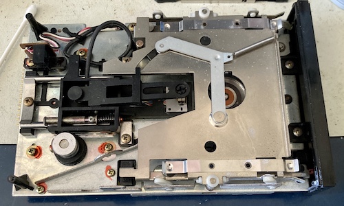
The drive in general is very different from the Amiga Chinons I’ve worked on before, although I was able to find a vaguely unhelpful manual for a double-sided F-354 on Bitsavers.org that had a pretty strong physical resemblance. Rather than a jackscrew, on the F-353 there’s some kind of external shaft that pushes the head shuttle around, using a leaf spring to clutch the two together. I considered that unusual, and I did hear a lot of grit when I slid the head back and forth, so I tried to pack some grease into the sliding interface, and everything else that I thought was able to move.
The only thing I found slightly askew during my lube-fest were rusty springs on each of the lower carriage “holder” pins, but they still moved and retracted fine when a floppy disk was inserted. Once I was able to eject a disk and have it go flying out of the drive and onto the floor, I figured I had greased enough, and hooked the drive back up for a slightly sketchy test.
Although the computer still hung, I noticed three new things here. One, the disk access LED was dimly lit for awhile on startup until it became brightly lit. The second new thing is that the drive now made little clicking sounds periodically when a disk was inserted, like it was attempting to read a sector over and over again. Last, if I waited long enough with a disk inserted in the drive, the computer would eventually “give up” and go to the 6601SR WORLD startup screen. Not so if there was no disk inserted. It would spin the spindle motor forever in either situation. Very odd.
The head shuttle wasn’t stuck, and I couldn’t think of anything else to grease up (I even managed to spray everything on my workbench with the stuff, which smelled great and was so fun to clean) so, with the mechanicals taken care of, I began to inspect the drive’s electronics.
This floppy drive’s electronics are split into two boards – what I’m going to call the “logic board” and the “spindle motor board.” The logic board contains a bunch of high-pin count chips and a ton of surface-mount passives that probably help interpret the flux signal coming off the read/write head. It’s also the part that talks back to the computer, controls the head motor, and presumably uses the information coming back from the spindle motor board to figure out what’s going on.
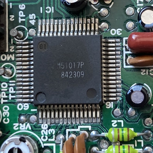
There’s a big Mitsubishi M51017 QFP on the Chinon drive’s logic board, which seems to encapsulate most of the interface logic. I couldn’t find any datasheets on this chip, but did find an IC scrapyard site that referred to it as “programmable logic.” I don’t know exactly what kind of programmable logic it would be – maybe a CPLD at most, since it was made in 1984. Honestly, I expected some kind of off-the-shelf floppy drive IC, but maybe the technology wasn’t mature enough in 1984 to provide a wide enough selection. Check out those cool angled traces at the bottom.
On the spindle motor board is all the spindle motor-driving hardware, including the index sensor. The motor board itself is very unusual - it’s a super-thin PCB that has somehow been bonded to the metal plate that holds the motor. All the components are surface-mounted on it, including the through-hole electrolytic capacitors. I popped off one capacitor, saw that it was bipolar, and put it back on. Motor drivers are weird stuff.
At first, I figured I could unscrew the tempting screw on top of the spindle motor counterweight/cover, but I just stripped the head a bit. It looks like the screw is epoxied in there, which I guess is a good thing for the requirement of “not flying apart during operation.”
On the side of the cover lay a four-wire component that I believed was my index sensor, because it looked just like the crank trigger sensor on a car engine’s timing circuit. Inside the spindle motor cover, there’s a magnet attached to the motor, and when it spins past this sensor, the hall-effect sensor picks it up and knows what angle the disk is currently rotated to.
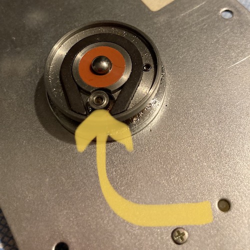
There’s a little leaf-spring-loaded tab on the spindle itself that grabs onto the rectangular second hole in the bottom of the floppy disk, and that’s what drives the disk’s rotation. It’s a pretty clever little system, and I enjoyed learning about it, but I’d enjoy it even more if it would end up with a working floppy drive.
The rabbit hole of chasing down faults ended in me desoldering a rusty-looking 74LS14 from the floppy controller PCB, finding out that it tested out just fine, and then socketing and reinstalling it.
A FlashFloppy Intermezzo
A quick break before I continue with my riveting description of reverse-engineering an old floppy disk drive.
As previously mentioned, in order to make sure I wasn’t crazy, I used a Gotek floppy drive emulator, pulled from the Sharp X1turbo, to test the floppy controller. Since the Gotek was already flashed recently, and configured for Shugart mode to work with the X1, I figured the floppy emulator didn’t need any more changes to work properly in the Mr.PC.
Indeed, after minimal effort, I managed to boot this Hudson Soft compilation disk just fine:

It’s weird that there’s this extra character floating at the top of the menu, but it didn’t change over successive cold starts. Maybe a bad floppy image3?
I also noticed while watching the Gotek like a hawk that it was now displaying some interesting new stuff I hadn’t seen it do before on other computers. Admittedly, I wasn’t really watching this particular Gotek when it was running in the X1turbo, but it looked like the drive occasionally flashed up a track number for some kind of debugging purpose:
It turns out that this is showing the track/cylinder number and which side of the disk is being accessed. I’m not sure why I never noticed this before on all the other computers I own with FlashFloppy’d Goteks.
Despite that little bit of excitement, it does seem like the Gotek worked better than the “real” drive in the Mr.PC. Still not properly, but at least well enough to boot half of the images I gave it. This partial success might have been because, being flash, the drive ignores everything to do with motors (the line isn’t even hooked up,) or something else was still going wrong that prevented the other half of the disk images from working.
| Image | Format | Did it work? | Comment |
|---|---|---|---|
| Douga Saisei Azusa (v1.1) | D88 | No | Starts BASIC, but gets stuck trying to RUN"main; it should proceed instantly (see video) |
| FM Music Exercises (SR) | D88 | Yes | Loads to a menu after a really long time, flickering video |
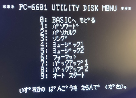
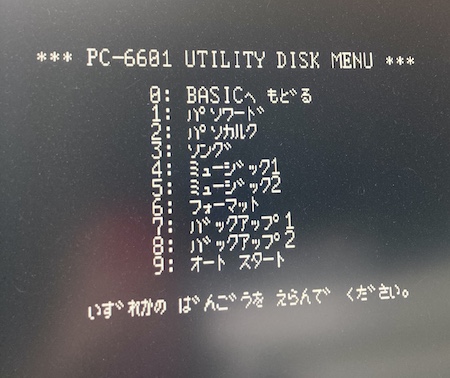
| PC-6601 Utility Disk | DSK | No | Sticks at the same “boot” screen as the original drive |
| Hudson Soft Best Hit Game Pack 3 | D88 | Yes | Corrupt(?) character in the menu, but loads very quickly |
Without a keyboard, it’s difficult to test any more functionality than this, but at least some images were loading.
Just to be on the safe side, I referenced this amazing set of hobbyist schematics for the 66SR to double-check the floppy pinout is. Indeed, it was Shugart. The only difference I noticed is that pin 2 is called out on the schematics as nDENS.
I added a configuration to the FF.CFG file on the USB stick to tell the Gotek to issue an active-low density signal on pin 2, and tested again. No change: images that didn’t load well before still didn’t load well, and everything else worked as before.
Back to the Real Thing
After playing with my multimeter and the pins on the hall-effect sensor on the floppy drive for a little while, I wasn’t able to determine any useful information with the Chinon floppy drive turned off. It was time to break out the logic probe, and I was looking to answer a few questions:
- Is the
/INDEXsignal ever issued by the drive? - Is the
/TRK00signal ever issued by the drive? - Is
/MOTORreally stuck on by the controller, or is the drive malfunctioning? - Which drive selects are being asserted by the controller?
- What signals differ when a diskette is actually inserted into the drive versus nothing?
After setting up an extremely sketchy test bench using an ATX power supply I found on the side of the road once, I hit paydirt almost immediately. Because I’d traced out the motor board previously, I was able to spin the motor by grounding the /MTRON pin, and watched the index pulses come off of the motor board and into the logic board. However, there were no /INDEX pulses observed at the drive’s output pin 8 - a number of the pins, not just that one, seemed to be open-collector (as I assume floppy buses are) and neither high nor low.
I traced the signal for index from the logic-board connector onto a NAND gate that was being used as a fancy inverter (0 NAND 0 = 1, 1 NAND 1 = 0) and then into the 2B input of a 74LS123. I’d never encountered a 74LS123, so it was time to do some datasheet research. After chasing it around a bit, it turns out that the index signal comes back out of the 74LS123 (after passing through both stages of it) and then is passed back to the NAND chip, to be NANDed with the disk-presence optical sensor.
I knew that this sensor already worked, because I probed it with my multimeter earlier when the machine was running. With no disk in the drive, it read close to 0V, and with a disk in the drive, it read close to 5V, so active-high. Then it ran around into the NAND gate again, where it was once again inverted, and served into pin 43 of the custom chip. All of this just seems to have been there to re-time the signal, and not to mess with it in any logical way.
The important thing to take away from this is that the index signal is NAND’d with the active-high disk presence switch. That effectively means that if there’s no disk in the drive, then the index signal will not be received on pin 43, and the custom chip probably interprets this as “don’t bother pulling the index output line low.” It likely also doesn’t emit anything when the drive is not being selected, so two drives on the same floppy cable don’t fight each other by spamming the bus with index pulses.
In the end, a missing index signal can’t be the cause behind the non-booting, because in that case it would be crazy for the floppy disk controller to be waiting on an empty floppy drive for an index pulse that will never come. So a missing index signal is not the cause of this problem after all.
Another, Greasier, Test
I’m a big fan of Keir Fraser’s work, and one of the latest things he’s done is the Greaseweazle floppy disk flux dumper/writer. Not only is it a useful device for writing floppies to weirdo formats (like the X68000) but I figured it would also be useful to test floppy drives with.
I bought a board just before Christmas 2020, but it sat around for awhile because I didn’t want to use it without setting up a nice enclosure for the whole setup first. Of course, then this floppy drive landed on my desk, so it was time to test it out.
Initially, I planned to do something simple to test the Chinon. Erase a double-density floppy disk, write an image to it, and then read the data back to see if it made sense. Unfortunately, no matter what I tried, I couldn’t get the spindle motor to turn, which made the Greaseweazel client bomb out, complaining of a missing index signal (since the motor wasn’t running.) This was a very confusing change from the Mr.PC, where I couldn’t get the spindle motor to stop spinning.
Luckily, I could reset the MOTOR jumper on the drive to the other position. The jumper selects which pin on the floppy bus that the drive’s motor will listen to. Once moved to the non-factory position, the motor now listened to pin 2, and I was able to force pin 2 to be always “on” with the command:
% ./gw pin 2 l # set pin 2 to always low, starting the motor
I had originally thought that the computer would turn the motor on and off at the right time to position the disk, but it actually seems to just constantly spin the motor and then wait for the right “time” to come around, so sticking the motor on all the time does not seem to impede the read/write process, which was accomplished with these commands:
% ./gw erase # wipe the disk
% ./gw write \[Utility\]\ PC-6601\ Utility\ Disk_dsk.hfe # write an HFE-converted version of the disk image to the disk
% ./gw read dump.hfe # dump the disk back to an image for analysis
Computers are amazing.
Although it dumped both sides of a single-sided floppy image (I should have read the Greaseweazle manual first and specified better disk geometry for the read,) I was able to then open it up in the HxC utility and view the first track of the disk. I should have checked more of the disk, because… you’ll see.
However, there was what appeared to be reasonable BASIC keyword junk and strings inside the new disk image, as well as a remark that the drive wrote the track at “298 RPM,” and I was not yet comfortable with the HxC tool’s unique user interface, so I didn’t go looking much further at that time.
I set the jumper back to “MOTOR 1,” (driving the spindle motor with pin 16) and then actually read the manual for Greaseweazle. It turns out that adding the --drive 0 option makes the Greaseweazle microcontroller understand it’s operating in Shugart mode (the default is “IBM PC” style, which has a different motor pinout, integrated into drive selection) and the following complete command spun up the motor and dumped the floppy properly:
% ./gw read dump2.hfe --drive 0
So I know for certain now that the drive worked, and worked well, although I might have a few more pages of documentation to read before I can use the Greaseweazle effectively.
I knew that some images worked on my Gotek, so I wrote those images to real floppies and then tried to boot off the drive. Still no go; the drive would vrrt every second or so, and then eventually give up on reading the floppy and kick me into PC-6601 WORLD.
I sat and thought about why the Mr.PC couldn’t control the drive properly.
MOTOR
I decided I would trace the /MOTOR signal back from the floppy drive into the computer. If this signal came from the bridge driver chip on the logic board, then maybe the driver is bad, even though that same chip is moving the head around just fine. I did a quick check with my voltmeter - 0.13V between that pin and case ground – and traced it into a VC5025, which is a chip I’ve never heard of and can’t find a datasheet for, next to the spindle motor.
I was a little surprised that the rest of the floppy drive’s logic board didn’t have anything to do with the /MOTOR signal, other than passing it on from the pin on the computer-side bus. This means that the computer is sticking our motor on and nobody is getting in the way.
Buoyed by this new discovery, I decided to trace it all backward. The signal goes from the floppy bus connector on the controller board, into a 74LS07 hex buffer, and then finally into the custom chip on the floppy controller board. My heart sank at that last one: if the custom chip were bad, the chances of me fixing this machine were approximately zero.
I decided I would desolder and test the 74LS07 first in my TL866, just like the earlier 74LS14 that turned out to be just fine.
Desoldering from the weird square pads NEC used is surprisingly hard; there’s a lot of surface area and it seems to really want to cling to the pins the nanosecond you remove heat. I started out with my trusty spring-loaded solder sucker, but even with the vacuum desoldering gun, it took a couple cycles of adding and removing solder before I could get loose enough pins for a clean, safe pull.
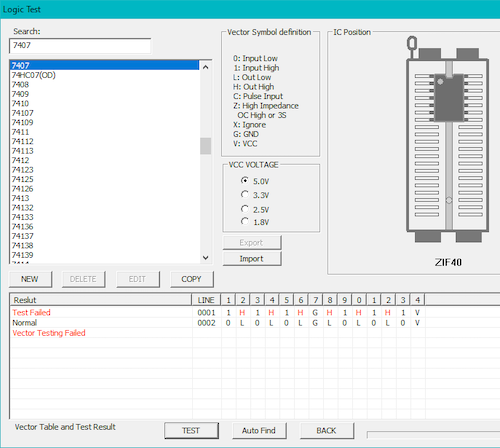
The tester reports that the 74LS07 buffer chip is bad. I had an initial rush of excitement, but then I wondered how the IC tester worked with an open-collector chip, such as this buffer. Would it just never report “high,” or was the tester smart enough to enable pull-downs/-ups?
I was very suspicious that the IC tester had screwed up, and moreso when I traced out the chip’s destinations. If the tester was accurate and the chip was permanently stuck low, then according to the Japanese schematics, the signals affected by this chip failing would be /MOTOR, drive select 0, drive select 1, and /STEP. It seemed like step in particular would screw up the Gotek by asking it to constantly seek to track zero, so trying to read/write anything on the disk past the initial bootloader segment would break. Yet, the Gotek’s LCD tells us it’s convinced that the computer has asked it to visit exotic places like “cylinder” 36 when loading up the Hudson disk image.
Luckily, the chip isn’t extremely expensive either way, although I was unable to find it at my local electronics store as they only carried higher-numbered “high-low” buffers. It sure seemed that a 74LS07 was an unpopular or at least obsolete part. I ordered a couple of replacements from Digi-Key. With a known-good new part, I could test the tester - and ideally I wouldn’t be out too much money if the software was wrong.
Unfortunately, it turns out that the tester software was wrong, or at least I picked the wrong test4. The new part failed the test identically, so I knew that it wasn’t to blame. Anyone got some cool ideas for what to do with, oh, five 74LS07s?
Next STEPs
I would have used a logic probe earlier, but there’s no easily accessible 5V and ground pins on this computer for my logic probe’s alligator clips to grab onto. I ended up ordering some test point “hooks” from AliExpress and putting together this little board, which took 5V and GND from the unused second floppy power connector and gave me reference voltages.
All of that kapton tape is to keep it from shorting against metal parts of the case, probes, etc. Can never be too careful! Why does it look ugly? Because it’s hard to cut kapton tape with children’s safety scissors, which is all I could find within reach when I was making the adapter.
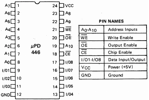
With the logic probe in play, I could now answer a bunch of questions I had about the boot process. The first stop, naturally, was the µPD446 SRAM on the floppy controller board. This RAM, I suspect, is used to cache the data read from the floppy disk so that it can be delivered to the rest of the system semi-asynchronously through DMA without blocking on the rest of the controller board. Faster floppy performance, faster computer, everyone’s happy.
If that SRAM were to be bad or otherwise acting weird, it was probably going to cause some data corruption, and maybe even make the computer make bad decisions based on what it was retrieving. I checked the select lines on the SRAM first, to see if the chip was even being used.
With no disk inserted, the SRAM chip didn’t appear to ever be selected. The nearby 74LS245 buffer also seemed to be working properly; its output enable and direction pins were being pulsed more frequently with a disk inserted versus not.
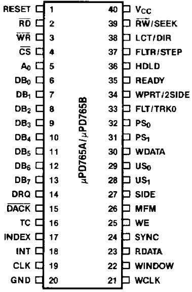
Probing the µPD765 floppy disk controller, I saw chip-select activity but nothing on the DMA pins. I was kind of hoping there would be a stuck DMA transfer or something causing the hang, but no such luck.
Since the WR (write) pin was never asserted, and since I was trying to diagnose a boot problem, I assumed that I was potentially looking at an issue with the data being read back, and ignored all of the pins that had to do with writes:
- WCLK (write clock);
- PS0, PS1 (requesting timing shift for incoming write data);
- WE (write enable into FDC);
- WPRT (write protect sense on the disk)
I had a further suspicion that since the Gotek was “kind of” working, the problem might lie in some timing/analogue aspect of the mechanical floppy drive that the floppy controller can no longer compensate for.
I did notice that the “read data” pin was pulsing even with no disk inserted, which I considered at first to be a little weird. The datasheet for the µPD765 did not actually explain how the drive acts with no disk inserted on this pin. My guess was that since the “read data” pin is the raw signal before clock-data separation, the periodic pulsing was just the clock signal. With the disk removed, the drive won’t generate an index signal, so I suspected the computer wasn’t doing anything with it and moved on.
I decided I would break out the frequency counter and check the clock inputs. Although the 16.000MHz crystal was a little bit off (at 16.142MHz) it probably wasn’t a significant problem. From reading the datasheet, I knew that, in MFM mode, the WCLK (write clock) pin should be showing 1MHz if the CLK was at 8MHz and 500kHz if the CLK was at 4MHz, and that’s what I saw.
I was getting really confused. It seemed like the floppy drive was working properly, and the µPD765 was working properly, which meant that the custom chip should be getting good data. And the parts of the system that the custom chip was controlling all seemed to be working as expected as well.
Was this computer broken at all?
More Research Needed
After looking at the excellent p6ers website, I noticed a small comment on the PC-6601 (not PC-6601SR) floppy disk page:
If the number of drives is 1 or more and a disc is inserted, the disc in the drive is read. Maybe [it is] checking if [the computer] can read the first sector. If this is not read correctly (not formatted), BASIC will not start “forever”.
Uhh.. is this what Hashi6001 was trying to explain to me by asking about the 0, 1, 2 floppy disk switch on the back? I suddenly felt very sheepish.
After doing a little more poking around, I found the PC-6601SR floppy disk page, which basically explained the same thing:
If no disk is inserted in the drive when the main unit starts up, the boot menu will not be displayed forever. → [You can confirm this for yourself] by leaving it on the actual machine for about 10 minutes.
Yup.
If some disk is inserted when the main unit starts up, the startup menu will be displayed after leaving it for about 1 minute. → [You can confirm this for yourself] with the actual machine. The disk [can] be anything, even a 2HD or unformatted 1DD disc will boot.
Yup.
I’m very grateful that this was documented somewhere, so that I didn’t end up giving up on a perfectly working machine and putting it back on the shelf. It’s odd that the 6601s don’t act the same way as the earlier PC-8001s, but they were made by different teams after all.
Okay, well, now that I wasted several weeks trying to figure out how the disk system worked, it’s time to try and make a floppy disk that this computer will actually want to boot. Since the Hudson image worked semi-properly on the Gotek, and the utility disk didn’t seem to, I decided I would try and convince the Greaseweazle to make it into a real floppy disk.
A Real (Bomber) Boy
I first wrote the Utility disk and the Hudson disk from the Greaseweazle in the way described above. When those disks were inserted into the Chinon floppy drive, the Mr.PC repeatedly tried to read them and then eventually gave up and returned to the “PC-6601SR WORLD” screen.
Since I knew that the floppy drive worked, I took this to mean that I had written the floppy images incorrectly, and started tweaking Greaseweazle settings. I tried limiting tracks to 0-39 and heads to 0 (“single sided” mode), trying other image formats than HFE (SCP was also supported) and standing on my head.
No luck, as any diskette I created from the Hudson images would just time out to the screen. I did notice that the spindle motor on the floppy drive would eventually shut off a little while after timing out, which is nice because the drive is pretty loud. When I get this thing working, it would be annoying to have the motor going all the time when I’m trying to work play videogames.
I went hunting again, and found the D88STRUC.TXT document that explains the structure of a d88 file. It mentioned that D88 is inherently a double sided disk image format, but some tools used $30 or $40 as a disk type flag to indicate that the disk is actually single-sided. It sounds like these might be a bad rip, and some PC-6001 emulators are smart enough to ignore it, which is probably the only reason these bad rips still haven’t been properly fixed yet.
I modified the Hudson image to test, by changing the byte at $1b from $00 to the 1dd setting of $405, and when I opened the modified version, suddenly the HxC image converter tool was reporting the disk as being 80 tracks and 1-sided, instead of 40 tracks and 2-sided!
Considering the HxC image converter tool was being used in both the Greaseweazle and Gotek-running-FlashFloppy, I was very suspicious that these images were a dump that was confusing the converter tool.
And indeed, when I applied this $40 fix to Douga Saisei Azusa and put it on the Gotek, it booted and ran properly! This was a little bit of a surprise, since 1D floppies are only meant to be 40-track in the first place, but in retrospect, I suspect it has something to do with the “double step” backwards-compatible behaviour of the 6601SR. More on that in a bit.
It seems that before, the Gotek had been convinced that it was only a 40-track image on an 80-track disk, and so when the computer told the floppy drive to seek to track 47 during program initialization, it would just read “blank” data. Somehow, changing the media type to 1DD has convinced the HxC tool that the image is actually an 80-track image for an 80-track disk. Even though that’s not entirely true, it seems to have worked out.
Chances are all of the D88 images, including the ones that booted and ran, had this problem. I was just getting lucky with the Hudson image, in that it hadn’t tried to go above track “40” yet. I wrote a quick Python script to modify d88s for this purpose and filed it away.
SAMdisk also got confused, claiming 40 tracks when converting the d88 to a raw format and complaining about a lot of missing sectors, but correctly guessed that there was only one “head.” The number of “missing” sectors doubled on the hacked image, so I wasn’t very confident that I was doing the right thing here.
Raw images
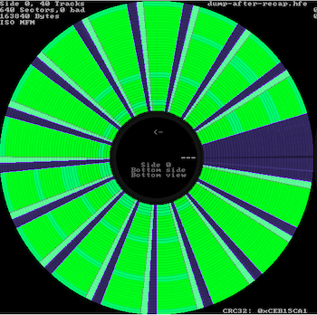
The NEC PC-6601SR utility disk, as well as a few of the games, are a DSK format image, instead of D88, and so this same fix wouldn’t work there. Between the hex editor and the size, it looked like these 163,840-byte DSKs were raw images (40 tracks * 1 head * 8 sectors * 512 bytes/sector = 163,840 bytes; the math works out), but the HxC tool interpreted them as 42 tracks long for some reason and converted them incorrectly when producing the resulting HFE file.
I decided to work on that, because I was on a roll. FlashFloppy lets you define your own geometry for raw disk images, so I figured I might just be able to trick the FlashFloppy into acting properly when it encountered these raw images.
After tweaking the configuration, I placed the *.dsk images, without conversion to HFE, directly on the USB stick and booted up. Each *.dsk image acted pretty much identically to before, and also how the actual Chinon floppy drive acted: bouncing on track 0, presumably trying to find the boot sector.
What was different between the interpretation of these d88 -> HFE images (even unhacked) and the raw *.dsk disk images that kept the boot sector from being read on the Gotek?
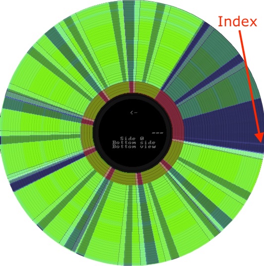
By taking a screen shot of the disk visualizer in the HxC editor and then overlaying them, I could see that the index mark and track 0 sector 1 overlayed perfectly. So it wasn’t an offset-from-index timing issue that was keeping track 0 sector 1 from being read.
Eventually, I tried changing the sector size from 512 to 256 in FF/IMG.CFG. Now the utility disk booted!
After a little more confusion, I eventually remembered to re-check the Japanese site that had the geometry for the “1D” disks: rather than the 40 tracks, 1 side, 8 sectors, and 512 bytes/sector that SAMdisk had reported and that I had used in FF.CFG, the format was actually 35 tracks (really 40, but the inner five are left blank, like on a C64) 1 side, 16 sectors, and 256 bytes/sector! I should have gone back to double-check this page, and not trusted in my faulty memory for these numbers.
I decided to lower my sights and focus on something simple: get the original disk drive working with a Greaseweazle-written formatted BASIC disk.
This way, the computer would boot, I could get started on building a keyboard adapter, and I could return the Gotek to the Sharp X1turbo so I could finish that project.
Don’t Be So Dense
Let’s figure out why some of the images would boot, but not run properly on the Gotek. Were they simply bad dumps? Not exactly.
These dumps are all for the PC-6601, but surely an SR is the exact same thing, right? Wrong - the predecessor model, the PC-6601, did not have the same kind of floppy drive as the 6601SR after all!
On the NEC PC-6601, the floppy drive was a single-sided, single-density drive (“1D”) which reads and writes 40 tracks. But on my PC-6601SR, I have a single-sided, double-density drive (“1DD”) which stuffs 80 tracks onto the diskette. This means that the head on my drive is physically narrower, so it can fit more tracks on the disk.
With original disks, this manifests as a PC-6601SR not being able to write to a PC-6601 floppy diskette. It can read it fine, but changing the flux for a track twice as wide as the head is apparently just not possible.
So if the head is too narrow, how does the 6601SR read a 6601 disk? The BIOS cheats, and checks the first few bytes of the boot sector. This works because track 0 is still the outermost track on both a 40- and 80-track diskette.
If the computer reads SYS from this sector, it knows it’s a 40-track PC-6601 disk, and it should tell the head to just skip every second track when reading. Since each track of a 40-track disk is twice as wide as the head, this “interlaced read” hack seems to work out pretty well.
If it reads RXR instead, the computer knows that it’s a real 80-track PC-6601SR disk, and it should try to read “every” track of the diskette.
So what was happening was this:
- The computer boots an image off the Gotek, and reads
SYS. - It puts itself into “double-step” mode.
- The software on the disk tries to seek to track 1.
- The computer asks the Gotek to seek to track 2.
- The Gotek reads track 2 from the image, and returns it to the computer.
- The software on the disk goes “what the hell is this?” and crashes.
When the D88 images were modified before to use the $40 (1DD) media flag, the HxC tool was apparently inserting blank tracks on every second track when it converted to HFE. This had the same effect in some cases, but would eventually break down in others. I didn’t realize that’s what it was doing. It was basically pure luck that any unmodified image, like the Hudson one, did anything.
I hex-edited a few of the un-hacked, 40-track D88 images to use the RXR header, and suddenly all of those images started working just fine. Now when the software asked for track 2, the computer would ask the Gotek for track 2, and the Gotek would return track 2. Everyone’s happy now.
Later, I bolted this patch feature onto my d88 and dsk editor tools, way after I had already converted all of the images I had on hand where the fix was applicable. Some images didn’t have an SYS or RXR header at all; I haven’t run those yet…
This problem was also happening when writing a real floppy with the Greaseweazle, because when you gave it a 40 track disk image, it would only write it to the first 40 tracks of the disk. The exact same phenomenon would happen on the computer.
I hacked up the Utility *.DSK image to have an RXR header, expanded it to 80-tracks, and then wrote that to a floppy. Did it work? Read on…
Real Disks, Real Problems
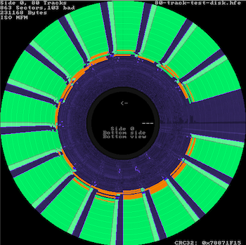
Back on the Greaseweazle, I decided that I would make a very simple “test” 80-track image with the F-353 drive. I would simply count up by the track number and write the bytes into the sectors. So track 1 would be all $00, track 50 would be all $32 and so on.
This way, when I read the disk back, I would immediately know if any data got corrupted – I’d see a byte out of place, or simply wrong. I didn’t expect what I got back. There were tons of errors. Lots of sectors came back with a bad CRC, and their bytes were mangled.
I felt extremely stupid – I wasted a lot of time trying to write real disks, when I should have been looking at the read-back more closely in the first place. This would have saved a lot of agony.
Track 0, which contained the boot sector, looked okay every time. However, I realized that when the drive was plugged into the Mr.PC before, I had been testing with the floppy drive upside down (so the exposed motor counterweight didn’t rub on anything.) Reading disks had a much higher error rate when that was the case - often not reading anything at all because of gravity fighting the clamp pressure on the head. Floppy drives: they need gravity, I guess, unless you’re in space.
After flipping the drive over so it was the right way up, the results got a lot better, but not perfect. Reads were different every time, and even reading a disk that was just erased in the drive didn’t produce a clean read!
The orange sectors below didn’t get erased fully, and were instead just damaged:
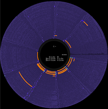
Cleaning the head with a q-tip and alcohol made it slightly better. Could this be the cause of my problems booting all along?
On “populated” disks, the bad sectors increased dramatically the closer I got to track 80. After about track 50 or so, the drive could no longer read anything at all. This is bad!
It got much worse the longer I fumbled with it, too.
This makes sense: the inner tracks are a shorter circumference than the outers, so they require a faster read/write cycle to maintain the same density as the outer tracks. Maybe something in the flux mechanism on the drive wasn’t “recovering” fast enough?
To confirm my theory, I tested reading one side of a known-good, factory-written, double-sided 720k disk (a LapLink install diskette for DOS) and everything looked fine:

Professionally duplicated disks are a good thing to have on hand to test floppy drives with, because the factories that master the disks have extremely strong magnetic flux when they write. Consumer floppy drives, which are presumably more power- and cost-conscious, leave a weaker flux. It’s possible that a professionally mastered disk is “loud enough” for this drive to pick up, but its write is simply too weak to be read well.
To rule out the media, I tried writing and reading the same images to the same disks using a Mitsubishi 1.44MB floppy drive I had lying around. That drive had its own problems (faulty track-zero alignment caused by a sticky head shuttle) which I had to resolve, but ultimately this “good” drive was able to read and write my test disk image using the Greaseweazle.
After writing the RXR-modified Utility disk image I hacked together using the “good” drive, I was able to boot a (modified) PC-6601 Utility disk for the first time ever on the original drive. Just look at it!
Both floppy drive cables worked with the Chinon, so I kept the original ribbon cable in there. It’s cheap enough to replace later if it becomes suspicious.
Cap-itulation
However, I still wanted to be able to write images using the Chinon, and write data to it when I was using the computer! I decided it might be time to tackle those caps on the Chinon’s motor board after all. They’re the only ones I haven’t replaced, and it was starting to feel like it might be a filtering issue. After building a cart with other crap I needed, I sent away for the two kinds of electrolytics in use - 1µF/50V polarized (7mm long) and 10µF/16V bipolar (11mm long).
When they arrived, I did the necessary contortions to replace the caps, and then ESR-tested the old ones. Every single cap on the motor board passed the ESR test with flying colours. Still, the job’s done: let’s see if The Internet’s Favourite Repair Method has produced a drive that can write images reliably.
…Huh.
I didn’t have consistent luck booting off that disk, so I ended up doing another round of cleaning and greasing the floppy drive, then wrote the disk again. That seemed to make a big difference, and I was once again able to write and boot disks. Although it seems the drive’s write function is much improved after the recap, it’s possible that this cleaning was the actual fix.
It may also turn out to be the case that the drive speed needs to be adjusted for maximum reliability – especially since I just changed out the Cs in a lot of RCs on the board. There are a lot of suspicious (unmarked) trim pots on the motor board, but I think I’ve done enough for now.
Conclusion
Phew. That was a lot of ugly diving into the seamy underbelly of floppy disk images, and the deep lore of backwards compatibility for a relatively unloved computer. If you held on this long, thank you for doing so.
There is some good news about how long it took me to get this thing to boot: it’s now spring! I took the 66SR out onto my deck to celebrate.
Now, though, the Mr.PC is ready to start on a new project: figuring out how I can actually type something on it. That would be a nice way to ring in the PC-6001’s 40th anniversary, which is this year in November.
Repair Summary
| Fault | Remedy | Caveats |
|---|---|---|
| Battery leakage on front panel PCB | Removed battery, replaced damaged components, sealed with new solder mask paint | |
| Second floppy drive bay’s dummy cover has busted clips | Not fixed at this time | |
| Floppies will not eject | Clean and grease floppy drive mechanisms | |
| Does not boot without floppy inserted in drive | Working as designed, apparently | Can get around this by setting the “number of floppy drives” switch on the back to “0” |
| Gotek/FlashFloppy fails to read inner tracks in *.d88 images, despite booting | Original images are bad dumps; modify media type to $40 (1DD) to allow HxC utility to convert them, or modify boot sector to use the RXR flag |
$40 is not the actual type of these images, but the HxC utility doesn’t support $30 (1D) |
| Gotek/FlashFloppy fails to read boot sector of *.dsk images | Configure FlashFloppy to use correct geometry | |
| Gotek/FlashFloppy fails to read inner tracks in *.dsk images, despite booting | Convert header to PC-6601SR format to disable FDC “double-step” mode | May cause images to fail checksum |
| “Known-good” 80-track IBM PC floppy drive didn’t write to the correct tracks | Dismantle, clean, and lubricate stepper shutter screw drive | |
| PC-6601SR floppy drive reads but can’t write | Replace motor board capacitors, clean again | All capacitors passed ESR test, so probably were fine |
-
A sticker on top of the machine warns that if you’re going to put anything but a PC-TV151 on top of it, you should use a PC-66M75K stand instead. The pretty plastics would be damaged by a heavy contemporary TV or monitor. Surprisingly, the NEC website still mentions the existence of this stand in an online technical note for the PC-KD351 monitor. ↩
-
If anyone from NEC is reading this, I would buy a Mr.PC Mini, but that’s probably less likely than virtually any other computer of the era. Just make sure it’s the red one. ↩
-
I found out after completing this repair that the Neo-Kobe set only contained a mere 48 floppy images, and the majority of them are stuff that came with the computer, like NEC utility disks, rather than huge games. Maybe I shouldn’t have been surprised that a computer that sold in such low quantities had very little software designed for it. Hashi has a tool to “wrap” tape images in a disk image, but I haven’t tried it, and I don’t yet know how this works with all the oddball handwritten tape loaders and timing-sensitive copy protection mechanisms out there in P6 tape software. ↩
-
In the time between writing and publishing this article, the new version of the MiniPro software apparently fixed this, changing the 7407 to “7407(OC/OD).” ↩
-
D88STRUC.TXT says that $30 is also used for 1d (not 1dd) disk image dumps, but the HxC tool claimed an image with the type flag set to $30 was corrupt and refused to load it. ↩