Becoming Mr.PC's Type
Tags: computer nec pc60 mr-pc pc6601sr keyboard homemade-hardware homemade-software keyboard-converter
Like the Sharp X1turbo, the Mr.PC is also not very usable without a keyboard. It’s yet another way in which NEC copied Sharp.
Background
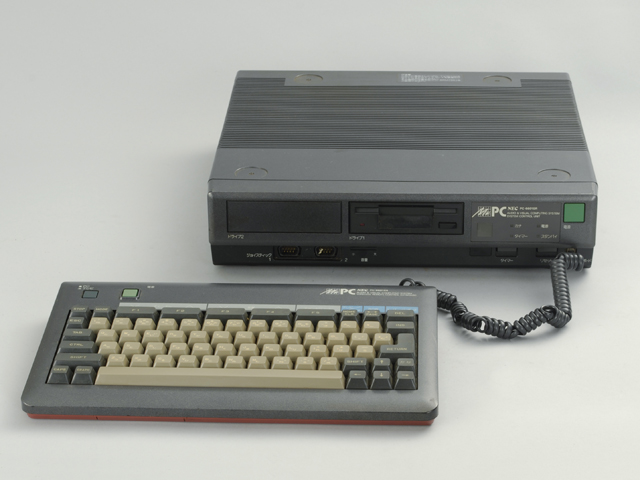
New readers to the blog (hi!) might be unfamiliar with the saga of the PC-6601SR. It’s NEC’s final model of PC-6001 8-bit home computer, released in 1984 while they were selling at least two other lines of home computer. Its claim to fame, besides being incredibly stylish – its tagline was “Roppongi PC” – was a wireless, infrared keyboard. This keyboard could not only do “keyboard things,” but also wake up and control the TV built into the computer’s monitor. Combined, the monitor + keyboard + PC-6601SR main unit were referred to as the “Mr.PC.”
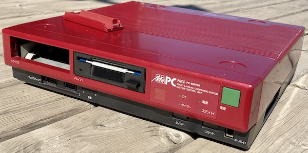
My own PC-6601SR didn’t come with any of that cool stuff, and was instead a rusty, scratched-up bare base unit (that looked good in the sun.) Not only that, but the floppy drive needed recap work, and there was a lot of confusion about incompatible disk formats and flaky pirated disk images. Once that got worked out, the computer was still not usable without a keyboard.
If I want to stand a chance of ever putting this computer through its paces, it’s time for me to build another keyboard adapter.
So why not just buy a keyboard? Well, even if you’re ignoring the recent trend of splitting keyboards from perfectly good computers, the original keyboard for the Mr.PC seems extremely hard to find in isolation.
Thinking about it, I could come up with a lot of theories as to why the keyboards would be difficult to find:
- The keyboard is wireless infrared, so it’s more likely to get separated from its original computer;
- Because the keyboard is wireless, it needs batteries to work. Those batteries are leak-prone AAs, so chances are that many stored keyboards became rusted out internally from battery damage, and then tossed. Its battery door seems to get lost, too: there are hobbyist-made 3D-printed Mr.PC battery door replicas for sale in Japan;
- Although I’ve never seen the inside of the keyboard, the key switches might be the same corrosion-prone Alps captive-dome switches used by the PC-6001mkII, leading to “broken” keyboards getting tossed due to the complexity and cost of repair;
- They just didn’t sell all that many Mr.PCs, and the people who owned them quickly replaced them with something newer and more compatible as it became available.
As a result, I could not find an original keyboard for this computer, not even for sale. This is different from many of the other Japanese computers I’ve collected, where the keyboards exist, but are sold at a price that I can’t justify.
For the Sharp X1turbo, I built my own PS/2 keyboard adapter rather than pay crazy auction prices. That worked out fairly well, although the firmware is a continual work-in-progress, so I’ll be building on that success (if you can call it that) for the PC-6601SR.
Yes, It’s Another Keyboard Adapter
I spent a lot of time researching keyboards before the computer even shipped, trying to figure out what the keyboard pinout and protocol was. It didn’t help that the Mr.PC was primarily famous for having a wireless keyboard. Thankfully, NEC’s engineers were paranoid enough to still support hard-wiring the keyboard, rather than demand that it only be available over infrared.
I think it would have been nice to build a whole replica keyboard that resembles the original and offers up infrared functionality, but after reading up on infrared data communication, my head started to swim. I’d have to figure out all this stuff anyway, so I decided to start smaller, with just a wired connection.
Eventually, I was reading Twitter over my morning coffee when I discovered that Ken-chan’s Home Appliances (@kadenken on Twitter) in Akihabara posted a homebrew product called the Mr.PC Keyboard of FB, made by hardware hobbyist Niga HP. It’s a sequel of sorts to his previous Mr.PC Keyboard of MSX, which is an MSX cartridge that emits infrared light from an LED. This lets you, in effect, use an entire MSX computer as a wireless keyboard for your Mr.PC.
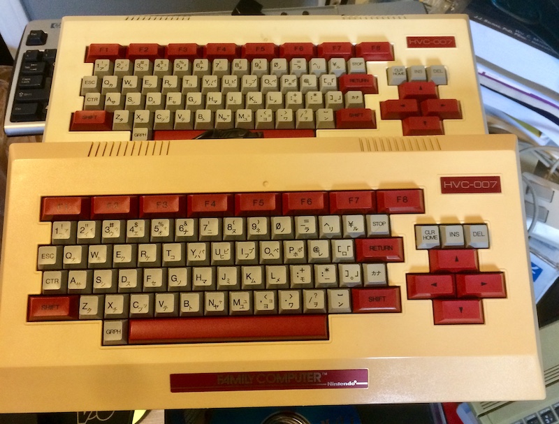
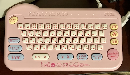
What’s the “FB” part stand for in this new adapter? Family BASIC, as in the cheap Famicom Japanese keyboard of which I had a bunch already lying around to use to build keyboards for other Japanese 8-bits. Great minds something something.
Ken-chan’s doesn’t ship internationally, although I have used a broker to order from them in the past. Unfortunately, while I was getting the proxy order set up, the adapter went out of stock, much like its MSX brother once did. I guess there must be more Mr.PC users out there than I thought!
A similar thing happened when I got the PC-6001mkII and needed the replacement keyboard PCB for it, also from KadenKen, and it took almost a year until more came in stock. I even made a trip to Japan in the meantime. While I was there, I checked if it had somehow been restocked in the physical store, but only the not-for-sale demo unit remained.
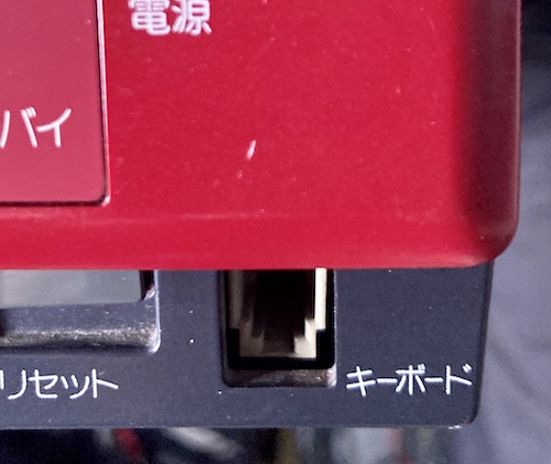
I immediately looked at all the pictures of the new adapter that I could, to try and figure out if it was feasible to make my own adapter, instead of waiting several months for it to come back. The first step was noticing the modular jack, which seemed to be wired in a “straight-through” configuration:
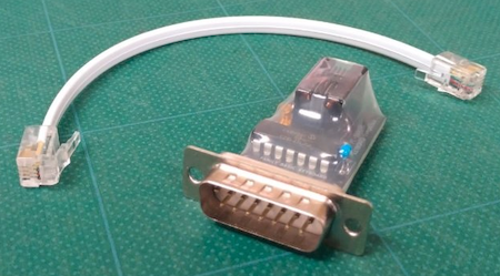
That’s just like the handset cord for a corded landline telephone:
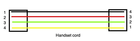
Realistically, since I’m designing one end of this system, I could use a regular “cross-over” telephone cord if I wanted, like the Coleco Adam keyboard does. But I wanted to keep it true to the original so as to avoid any future confusion and potential damage. Consistency: it’s good.
I couldn’t find my RJ crimper at the time, so I ended up ordering a cheap handset cable from AliExpress. I wonder if this came from back-stocked inventory, or if there’s a factory somewhere in China still cranking them out?
When doing my research on the rest of the project, I had a small stroke of luck that an amazing hobbyist had reverse-engineered the schematic for the 6601SR (including keyboard) and 6001mkII. There’s even a companion article containing the datagrams and keycodes!
From this fantastic set of schematics, I learned that inside the original keyboard, there is an 80c49 microcontroller on an 8MHz clock. Unfortunately, the 80c49 carries its own ROM, so the schematic alone isn’t very useful for figuring out a protocol, and I obviously don’t have one on hand to dump. However, it does let me figure out that apparently two of the four pins of the RJ9 connector just go to ground. The other two pins go to the T1 input of the 80c49, and the P14 bidirectional data pin.
I was a little surprised that no power supply was carried on the cord. Apparently, you are meant to have four “AA” batteries loaded into this keyboard even when it’s plugged in - there’s no provision for power source switching. “AA” battery leakage over the years might explain why there aren’t too many of these keyboards left in the wild…
Update: There is in fact a +5V rail exposed on the port, which is enough to power my keyboard adapter from the computer.
One interesting thing is that the data for the infrared emitter appears to come out of 80C49 data pin P17, and the “PC/TV” switch on the original keyboard is dedicated to input T0, which seems like a waste of a pin when you’re already strobing a matrix – it probably is broken out so that pushing the button can trigger an interrupt to “wake up” the keyboard’s controller when it’s not in PC mode, and is not scanning the keyboard in order to save power. The schematic also backed me up with a note that “the pin numbers are reversed from the main body,” which is another confirmation of the handset-style pinout.
There also appears to be no infrared receiver on the keyboard side, so we can infer right away that the protocol must be unidirectional. The keyboard sends signals to the computer, but the computer doesn’t tell the keyboard anything in return, just like on the X1turbo.
Infra-Rad
During the course of my research for this project, I read online that you could test the function of the PC-6601SR’s infrared receiver by pointing a TV remote at the front of the computer and pushing the buttons. While the TV remote’s packet is unlikely to be decoded into anything useful, the “standby” LED on the front of the computer will blink when it is receiving any infrared data at all.
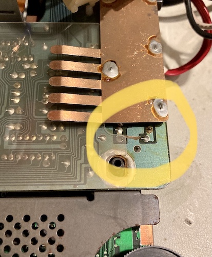
Since the infrared board had some suspicious-looking cut traces, I figured a fun afternoon activity would be to see if the receiver was working at all. If someone in the past had forcibly disabled the receiver to fix a problem, then I’d rather know about it now than after I’d built some infrared-emitting hardware only to find out it didn’t have a snowball’s chance of working.
I borrowed the remote for my crappy Vornado floor fan, and pushed some buttons while pointing it at the front cover of the PC. The green standby LED rapidly blinked in what I assume is some relationship to the incoming data. So that hardware is working, or at least attempting to work.
I also found out later that this light also blinks when the wired keyboard is communicating with the computer, which was a welcome diagnostic feature that helped me figure out the adapter. More on that in a bit.
Sending Mixed Signals
I’d found a couple of experiments with sending key signals to the Mr.PC without having the right keyboard. There’s a great writeup here by mm (the author of the iP6 emulator) using a logic analyzer to try and figure out the signals from a real keyboard. Although the entry seems inconclusive, the task must have been ultimately successful, because they published a key code table and then published an infrared keyboard emulator for Windows - complete with source.
Ultimately, I found and used the sbeach entry about the keyboard protocol. I found everything I needed to know there, starting with the datagram. As always, I am thankful for Esubi’s hard work.
You send the same datagram for both infrared and serial communication, although the timing is obviously quite different for infrared. As stated above, I’ll concentrate on serial for now.
Packet information looked pretty straightforward to send. Auto-repeat is handled on the keyboard side; no make/break nonsense required. Very simple.
Bits are distinguished by timing. Based on Esubi’s measurements, “1” is a high signal held for 501µs and a low signal for 209µs; a “0” is high for 149µs and low for 209µs. I’m guessing that there are more exact values somewhere, but if it works… steady state for the output signal is a high pin.
I groaned and rolled my eyes when I realized, just like the X1turbo, the PC-6601SR also has a “game mode” for sending important video-gaming keystrokes more frequently. This “game packet” sometimes (but not always?) precedes the regular key packet and holds the instantaneous state of the game keys STOP, SPACE, SHIFT, and up/down/left/right cursor.
Building the Hardware
It took me longer to find where I had put the handset cord I bought months before the Mr.PC arrived, and then give up and buy another one, than it did to build the breakout board and write the demo code.
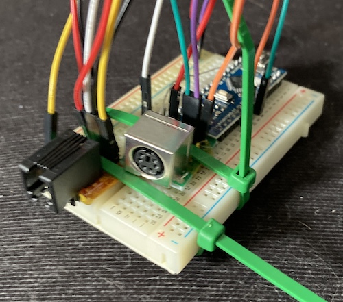
I made this ugly looking little breakout to hold the phone jack. I also added a 33Ω current-limiting resistor to the “data” line of the breakout in order to help protect the Arduino, as suggested by Esubi.
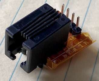
There are two “grounds” - that’s how the MrPC knows that a keyboard is connected. Pin 2 and pin 4 need to both be grounded, but only pin 2 is the computer’s ground. Unless pin 4 is also pulled low, the computer will happily ignore anything you spam into the data pin, pin 3. I don’t think I would have figured this out on my own.
My first draft software just sent the “0” key over and over - that way, when I booted off the Utility floppy, I could push it to kick myself into BASIC. This was the technique I did on the X1, although there I sent “T” so I could get into the timer sub-screen of the boot ROM.
Zero on the Wire
I had no real luck with my first draft of the code. I could see the “standby” light on the front of the case flicker, indicating it was parsing my packet header properly – flipping some bits around to test made this stop working. But: nothing would seem to be interpreted properly.
Going back to Esubi’s documentation, I realized that I was missing two key components: a parity bit, and the logical negation of the entire character byte and control bits! I had misread the timing diagram initially and thought that the second byte was just an illustration of how the signal repeats… but it wasn’t.
After some more reading, I determined that the basic PC-6601SR keyboard protocol goes something like this:
- Send the “wired” header - low for 2485µs, then followed by a logic “1” – high for 501µs, low for 209µs.
- Send the control bits in least-significant-bit order. Every time you send a “1,” toggle the parity bit. Do not toggle when you send a 0.
- Send the keycode byte in least-significant-bit order. Every time you send a “1,” toggle the parity bit.
- If the parity bit is 1, send a logical “1,” else send a logical “0.”
- Send the logical inverse of the control bits again. Do not toggle the parity bit here.
- Send the logical inverse of the keycode byte again. Do not toggle the parity bit here.
- If the parity bit is 1, send a logical “0,” else send a logical “1.”
This extra parity and inverse checking is very paranoid for a wired protocol, where you can be reasonably sure that the keycode will reach the end of a couple feet of copper1, but I assume this was meant to make the infrared keyboard more reliable in the event of phenomena such as strobe lights, fog machines, cats, and solar flares.
Again, Esubi’s thorough documentation was essential to figure this all out. I am extremely grateful.
When I tested this working version, I picked “0” for BASIC, which jumped into the BIOS’s “select a BASIC” menu. Unfortunately, there is no option “0” on this menu, so it just sat there for awhile until I turned the computer off. Two machines pitted against each other in a battle of wills, forever.
I changed the code to send the keycode for “1,” and on the next boot, it kicked me into BASIC and selected option 1 from the resulting menu, trying to run a program called pword, which crashed at some ungodly high line number. This could have possibly been because of the sketchy way the floppy image was written, a bad dump in the first place, or just because this utility disk wasn’t designed for the SR.
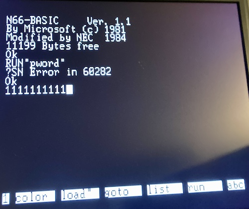
But… then the computer began to slowly fill up its BASIC prompt with glorious 1s!
With a working proof of concept, it was now time to really push my luck and implement PS/2 keyboard reading. For that, I’d need my only Japanese PS/2 keyboard…
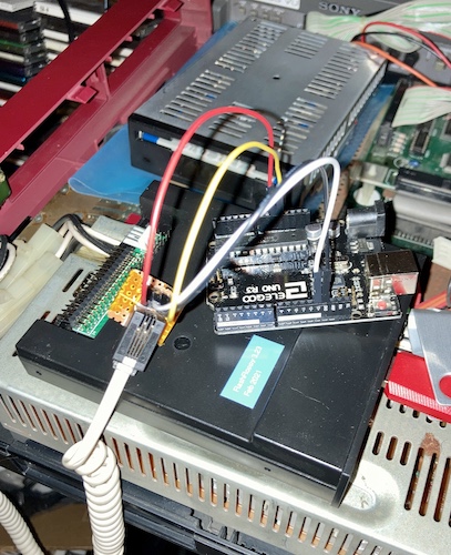
…and a better way to hold my pile of sketchy boards. Why not a ziptie to hold my PS/2 breakouts on top of 4P4C breakouts, on a protoboard with a knockoff Arduino Mini board?
I’d be lying if I said I wasn’t proud of this.
Hello Keycodey
Now was the time of thrashing, where I slowly change my goals from “something on the screen, hooray!” to “why doesn’t this particular key freaking work?”
I went through a bunch of backflips to convert from the PS/2 library’s “helpful” ASCII-ified keycodes to the PC-6601SR’s expectations. It involved a lot of hack code, and at least an hour of pulling my hair out, only to realize I was sending the header twice in a copy-paste accident.
It appears that the keyboard library always returns uppercase ASCII for English letters, so I had to explicitly downcase lowercase letters before sending when shift wasn’t pressed. I didn’t have to do that for the X1, because it interpreted uppercase ASCII as lowercase if the “shift” flag was turned off.
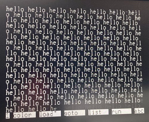
Through some trial, error, and strategic serial logging, I got a glorious 10 PRINT "HELLO" 20 GOTO 10 going. In fact, it was scrolling so fast that I couldn’t take a picture of it without the shutter ghosting it. In N66SR BASIC mode, this computer seems to really fly compared to the PC-6001.
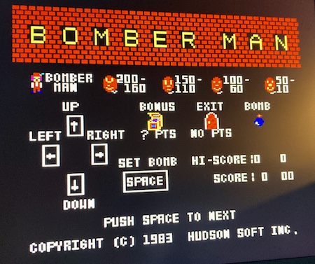
I was also able to get into Bomberman.
Yeah! Screw you, balloons.
This is definitely not the friendly, pudgy Bomberman that we know from the later games. His loveable form was only established after this, on the late-1985 Famicom release. Wikipedia says that the 1983 game was originally meant as a tech demo for Hudson’s BASIC compiler, which has to make it one of the most successful demos in human history. Get it? Human?
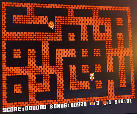
Unfortunately, once the game started, I discovered that the cursor keys didn’t work. All I could do was whack the spacebar to lay a bomb and then watch him die in a surprisingly horrific way.

I suspect this lack of response to key presses is because I haven’t implemented “game mode,” which is definitely something to aim for in a later version. For now, though, I can write simple BASIC programs, and put the PC-6601SR back to work.
Conclusion
The PC-6601SR is now a working computer, or at least one that I can use with keyboard input. Most of the work for this was actually done years ago, when I first picked up the computer, and I hadn’t bothered to write up an article about the converter yet because it wasn’t “done-done.” For instance, it’s still a huge janky pile of wires that I keep in the box with the PC-6601SR.
In recent months, I decided that it would be better to get the code out rather than worry about making it perfect, so that it can help others, as Esubi-san has helped me.
You can find and download the PC-6601SR/Mr.PC keyboard adapter code here at my GitHub repository, which also includes some instructions for how to assemble and wire the hardware. Of course, any fixes are very welcome.
In future versions, you bet I’ll be getting that “game mode” working. I’d love to figure out how to make infrared play nice as well, and maybe even put all this on a nice, reliable PCB.