Sony's Triple Seven
Tags: computer sony smc777 pickups capacitors corrosion gotek repair
Sony doesn’t like to talk about their SMC-777 very much, but this unloved middle child represents an entire parallel universe of Japanese 8-bit computing. Today, we’ll take an extremely battered example and get it working again.
For the last year or so, I’ve gotten interested in getting a Sony SMC-777 of my very own. Part of it is because I got to play with an SMC-70, its more professional predecessor, at VCF Midwest. The other part is because I want to try out its very strange Z80 assembly language. How can a Z80 assembly language be “strange?” You’ll find out once this thing is fixed.
As I said above, Sony began development of micro computers with the SMC-70. That machine is Z80-based, with some truly impressive specs for 1982. 64k of RAM, high-resolution digital and analogue RGB, and add-on features like teloppers placed the machine above the competition, especially for the price. Oh, did I mention that it was one of the first computers to come with Sony’s then-new 3.5” floppy disk drive?
In keeping with the rapidly-forming Bubble Era, Sony commissioned the development of all-new software for it. A whole new computer needs a lot of software and documentation. They did their own non-Microsoft BASIC, banged out a CP/M-80 compatibility layer with graphics support, and built a bunch of games and applications. They released this machine in North America, even pursuing the porting of AutoCAD to the system.
Less than a year later, Sony did a followup to the SMC-70. This new machine, the SMC-777, ported the SMC-70 platform to what seems to be a much cheaper construction, intended for home use. Unlike the original, the SMC-777 seems to have only been released in Japan, and it came with more software, modified to have a friendlier front end. This machine was later followed up by the SMC-777C, which is essentially a 777 with an internal expansion board installed to support 4096-colour palettes.
None of these machines appear to have been an enormous seller, despite the hard work of fellow Sony labelist Seiko Matsuda to market them. Although I had no luck finding concrete sales data at the time of writing, I do know that Sony was one of the most enthusiastic collaborators on the MSX standard when that appeared. No wonder, if they were bankrolling the development of an entire software ecosystem.
Buying One
Searching Japanese auctions off and on showed that sellers have no idea where to price these machines. While demand did not appear to be strong in my experience, the initial listing prices are usually very high. Many times, I found them listed only as full manual-and-disk sets, marked up to collector prices.
Eventually, I located this one, which, to say the least, is very incomplete. Even though it’s probably one of the cheaper ones to trade hands, I still feel like I paid way too much for this machine. Here it is.
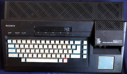
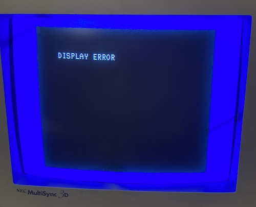
Not only are there cosmetic flaws, but there appears to be a mysterious “Display Error:”
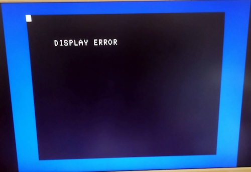
A quick web search didn’t turn up any obvious culprit for this error, but I was hoping it was something simple like video-RAM and not something complex like the HD46505 CRTC. However, you can push Reset, and the machine seems to run after this error is produced, so either the error is not actually very important, or it explodes later in a way that couldn’t be tested. Why couldn’t it be tested? Probably because it’s missing its floppy drive:
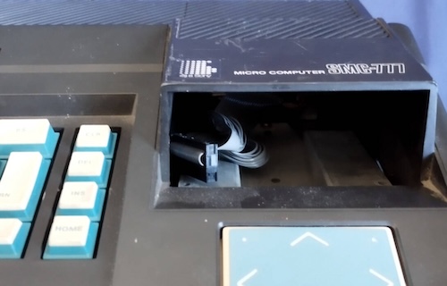
The Sony SMC-777 floppy drive (reportedly “MFD-32V,” but reports also indicate it’s the same as the OA-D31V used in HPs) is really special, too. Not only is it a very early 3.5” floppy drive (Sony innovated the format,) but it’s a weird physical size, its 26-pin pinout is unusual, disks are only 70 tracks, and it’s a single-sided drive. Not having the drive reduces the value of the machine quite a bit, which is probably what made it affordable for me. I suspect that this drive was pulled to use in another SMC-777/C.
Those parts-pullers didn’t even leave the bezel behind, which is just further evidence that this was scrapped to save another machine. I’ll have to figure out something there too.
Although I suspect there must be some kind of hidden machine-language monitor in ROM as the SMC-70 had, the SMC-777 really wants to be booted off a floppy disk to do anything more interesting than “please insert disk.” Rather than try to source a replacement drive, I’ll be making a quick wiring adapter and using a Gotek.
DISPLAY ERROR
Let’s figure out the display error first. While the computer was on its way to me from Japan, I grabbed a copy of the BIOS ROM and did a strings check on it. The error strings TURN OFF, MEMORY ERROR, and DISPLAY ERROR are the first three English-y strings to pop out of the file. DISPLAY ERROR is at offset $19c , so I disassembled the ROM using z80dasm and went looking for any references to that offset.
There’s only one reference to that offset, where it seems to be the fail-out condition on a loop that repeatedly checks I/O port $1b for some kind of status flag. What is port $1b ? Oddly, this SMC-70/SMC-777 I/O map says it’s the keyboard controller’s status register. Why would it say DISPLAY ERROR for a keyboard error?
I decided to jump into MAME’s debugger and see if I could force it into showing the DISPLAY ERROR myself. Sure enough, if I trapped on reads to $1b , I would end up in that block of code. If I forced the program counter over the next ret, to $13e , I’d be able to get the same error:

However, it doesn’t make sense that that code ever ended up there. Surely it was just in the neighbourhood of the keyboard-reading code, and someone else jumps to it when angered. Some code up above, in $b9 , has a jp nz, $013e instruction that sounds more like what we’re looking for. Somehow, z80dasm completely missed this jump when trying to figure out the labels.
I restarted the emulated SMC-777 and set a breakpoint there. It looked like immediately before doing this comparison, it is reading from port $80 . If we go back to the I/O map, it is reported that port $80 through $ff are the ports through which you can read and write video RAM, with the cryptic note:
A[15:0]=GA[7:0], A[ 6:0]=GA[14:8]
That’s probably not important right now. What is important is that this error seems to originate from a bad read-back of video RAM, and so it’s failing some internal integrity check as I had initially guessed. As a bonus, I had noticed that, when firing the BIOS up in MAME, there was a lot of video flicker, presumably from the machine quickly writing stuff into this memory space to test it.
This wasn’t a totally unexpected outcome. When I was shopping for my SMC-777 over the last year or so, I had noticed that there was a seller on Mercari offering replacement 150ns µPD4164 DRAMs as “SMC-777 RAM.”
When it arrived, I popped the computer open, and immediately found a couple interesting things. I had screws of different lengths holding the bottom together, which wasn’t great. The top case’s wiring harness was left completely unplugged, which didn’t fill me with confidence. And the floppy cable was also unplugged from the motherboard, which just seems to be unnecessarily sloppy. Someone was in a hurry to close this thing back up.
Never mind – time to find those RAMs. I soon spotted a row of eight Fujitsu MB8264 DRAMs, but I couldn’t be sure they were video RAM. We know from the minuszerodegrees DRAM interchange table that they are the same as an NEC µPD4164, at least. Each of these makes 64kbit, so eight of them together makes 64kBytes. Checking Wikipedia showed that the SMC-777 has 64kB of work RAM and 38kB of video RAM, so I suspected that these were in fact the work RAM.
Wait. What the hell, 38 kB of video RAM? That’s an extremely strange number.
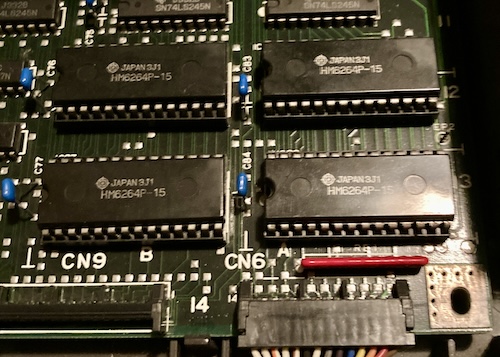
On the other end of the board, I soon spotted a group of four socketed Hitachi HM6264 8kByte SRAMs, which would make a total of 32kB, leaving 6kB still unaccounted for. Confused, I started looking around the board for more things that could be RAMs. I found three soldered-down 16kBit Fujitsu MB8416A SRAMs in the rough centre of the board: IC53, IC54, and IC55.
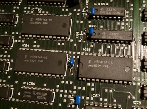
Without looking at the schematics, because I couldn’t find them and forgot to download them when I last saw them, I was guessing that each of these RAMs represents some equivalent data-structure to bitplanes or PCG for red, blue, and green video. Later, I found out this isn’t true. That flawed theory was based on the scientific analysis that there were three of them. (16384 * 3)/8 = 6144, or our missing 6kBytes of video RAM – if nothing else, the math works out.
Thankfully, the HM6264s were socketed. I could pop them out and give them a test with my TL866 to see if they were simply bad. While new 6264s aren’t exactly growing on trees, I did have a bunch of probably-good ones in my growing hoard of parts, and had at least one otherwise unrelated donor motherboard to source more from.
Unfortunately, the 6264s tested out just fine. I did notice that the funky sockets that Sony used were really crusty, so I gave them a spritz with Deoxit to see if that was where the problem was actually coming from.
At this point, I figured it would be a good idea to check if doing that re-seating actually changed anything. It had nothing at all to do with the fact that I didn’t want to desolder the MB8416s. Nothing at all.
Before I could test those SRAMs, I had to do a little bit of cleanup on the power supply for safety, and a video pinout check, but we’ll get to that later.
Turns out that: no, I hadn’t magically solved the “DISPLAY ERROR” message.
But I did notice something interesting about the t in “Insert.” Look closely at the edge of the cross.
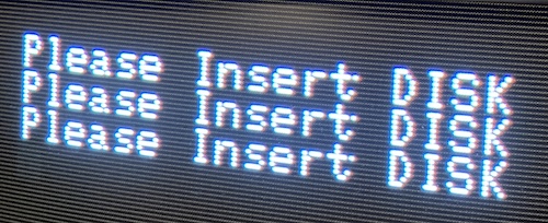
Here it is in MAME. Notice how the real thing has that extra dot?

Where is this extra dot coming from, and why is it on every line?
“PCG,” or programmable character graphics, is a common feature in character-based 70s and 80s computers. By allowing the user to redefine the font, a programmer can get the benefit of being able to draw whatever they want but retaining the fast performance of a character display. Essentially, it turns the text mode into a tile-based graphics mode, and the SMC-777 has one of them.
So if we have a corrupt t character, it stands to reason that it’s either in the ROM, or in the RAM where the PCG data is stored.
With some trial and error in the MAME debugger, I was able to work out where the font lives. The capital “I” lives at $248 , and the lowercase “A” lives at $309 . The characters seem to be 8 bytes long, with each byte one row of eight on/off bits, like on the TMS9918A. Going from there, I reckoned that the lowercase “T” must be at $3a0 , and it was.
Because ROMs are tough, I began to suspect this glitchiness was in fact coming from the PCG memory, which stores the character tile data. It’s 2kByte, so I realized that PCG must be one of the three mystery RAM chips. From this revelation, I now knew that the three mystery chips must be:
- Attribute (colour, blink, etc;)
- VRAM (text buffer;)
- PCG (character pattern data)
The larger 32k video RAM block is GVRAM, or “graphics VRAM,” and stores at least an entire screen (probably more) in bitmapped colour data.
Initially, I had assumed that the fonts were being thrown at the screen directly out of ROM, but upon viewing the PCG debugger in MAME, I saw that it was getting stuffed full of tile data during startup.
Indeed, if I changed byte $3a2 of the PCG RAM to $7d instead of $7c , I got something that looked a lot like the corruption that I was seeing. Subtle, but enough to trip a RAM check1. Seems plausible enough to start desoldering some chips.
One last question: which of the RAMs is the PCG? As nice as it is, I’d rather not have to desolder and socket all three chips on a 42-year-old board. Let’s see if I can use my brain, so I only have to remove one chip.
Since I didn’t have the official SMC-777 schematics (too pricey!) I decided to see if I could find a copy of I/O magazine. I am very fortunate that most of these have been scanned. The March 1983 issue of Monthly I/O is reputed to contain a schematic of the SMC-70. According to the table of contents, it did - on page 369. Japanese computer magazines were thick in the 80s, folks.
I found that, on the SMC-70, the PCG is written to an M58275P SRAM at position IC90. Not much to go on, especially since this machine has completely different RAM ICs, with different numbering, and has amalgamated a lot of the discrete decode logic for the PCG into its big Sony ASIC, so I can’t even do a continuity check from the pin to figure out which SRAM is getting selected in that event. Even so, this is a very thorough schematic, and I’m surprised at how much discrete logic was in the -70 versus the -777. I should come back here when I want to make an SMC-70 clone…
One idea I had was to write software or burn a custom ROM that hits the PCG RAM area over and over, and look for which of the Fujitsu SRAMs had activity on the “write” pin (21.) That seemed like a good idea, but it involves a lot of work. Surely we can figure this out without having to learn to assemble a BIOS ROM for a whole new system and its confusing I/O port scheme.
Okay, let’s try differential analysis. We know that text VRAM is written to continually during runtime (for printing more messages,) but PCG RAM and attribute RAM are only written to at startup, to set up the font and colours.
After poking around the internet again, it turns out that I got very lucky. Although the MB8416 is hard to find, it turns out that it is a 6116-derivative. 6116s don’t exactly grow on trees either, but thanks to my endless hoarding of garbage, I had some in my stash already.
Power supply check-out
Just as I was about to test the “Display Error” for the first time on real hardware, I decided to take a peek inside the power supply’s lid. Through the vent holes, I could see one cap with its heat shrink “skirt” pulled down, but more importantly, I saw what I believed to be corrosive circuit glue.
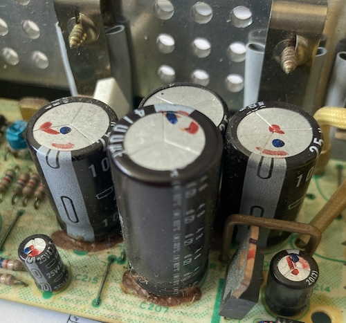
This brown goop is used to keep caps and other components still during use (caps vibrate as they are used) but a certain variety of it seems to pick up moisture from the atmosphere and corrode nearby components.
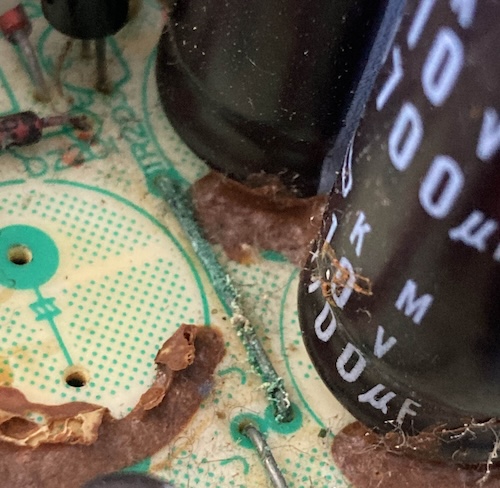
For instance, this jumper link tucked between two caps got really gross and had to be cleaned up. Having this go high-resistance or even open could be really bad for the power supply.
To remove the goop, I had to desolder all these caps. Although the power supply “box” is fairly tight, Mitsumi/Sony picked a very high quality set of components here, airflow seems good, and so almost all of them passed an ESR test with flying colours even 42 years later. If they hadn’t also used the brown death goop, I probably wouldn’t have gone in here at all.
| Capacitor | Value | Voltage | ESR | ESR good? | Comments |
|---|---|---|---|---|---|
| C103 | 330µF | 180V | 0.10Ω | Probably fine | Mains cap with sticky heat shrink on top… |
| C107 | 10µF | 50V | 2.10Ω | Bad (max 1.60Ω) | |
| C201 | 1000µF | 25V | 0.05Ω | Good | |
| C202 | 1000µF | 25V | 0.06Ω | Good | Heat shrink pulled down |
| C203 | 1000µF | 25V | 0.06Ω | Good | Number initially obscured by goo |
| C204 | 22µF | 35V | 1.15Ω | Good | |
| C206 | 1000µF | 25V | 0.06Ω | Good | |
| C207 | 4700µF | 10V | 0.03Ω | Good | |
| C208 | 4700µF | 10V | 0.04Ω | Good | |
| C209 | 4.7µF | 50V | 2.60Ω | Good | |
| C211 | 2200µF | 10V | 0.06Ω | Good | |
| C214 | 100µF | 25V | 0.96Ω | Bad (max 0.30Ω) | |
| C215 | 47µF | 25V | 1.15Ω | Bad (max 0.90Ω) | PCB stained underneath |
| C216 | 22µF | 35V | 1.74Ω | Bad (max 1.50Ω) |
As you might be able to guess, all the C1xx caps were on the primary side and the C2xx caps on the secondary side. Most of the failed caps were the small ones, which makes sense as small ones have less surface area to shed heat.
I then set about scraping the gunk off with a box cutter blade. Although I’m told that isopropyl alcohol works well to soften these, the only thing that’s ever worked for me is cutting it into chunks and pulling it right off the board. I cleaned up any remnants with alcohol, and then scraped all the corrosion off the wire link and sealed it with clear nail polish.
I replaced the failed caps, and put the good ones back in. I’m frankly very surprised at how well a lot of these turned out.
Even so, I did notice a bit of “hot electronics” smell after running this for awhile, and a bit of inductor roar on startup. I suspect there may be some latent corrosion in here adding a bit of resistance, or simply things are not specced to run on 125V and are vibrating in the audible range.
Output voltages seem fine for now, but I am thinking about popping a Meanwell in this sucker one day.
Gotek adapter
As we established up above, the SMC-777 has a very early Sony floppy drive. Of course, that drive, along with the bezel, is long gone from this for-parts 777. That’s inconvenient, because I would really like to be able to run some software.
My first stop was to adapt the Sony’s 26-pin cable to the 34-pin connector on the Gotek.
With a lot of the early Sony drives, they used a 26-pin interface rather than copy the 34-pin Shugart interface from the 5.25” floppy drives. Later on, it seems that the Shugart interface was adopted for other 3.5” machines, although I’m not sure who made the decision to make this happen. Possibly it was just done for compatibility reasons, so that you could use the same cable for 5.25” and 3.5” drives. If you know, let me know.
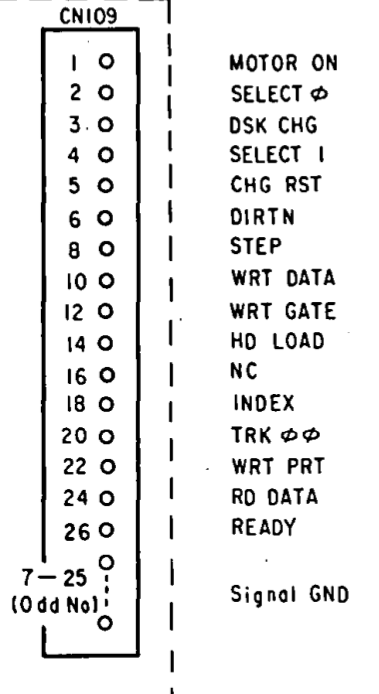
Note that this 26-pin interface is not the same as the Citizen 26-pin floppy interface, common in later laptops, which carries power on the cable. As confirmation, I went back to the March 1983 issue of Monthly I/O, which showed the SMC-70’s floppy drive pinout on page 379.
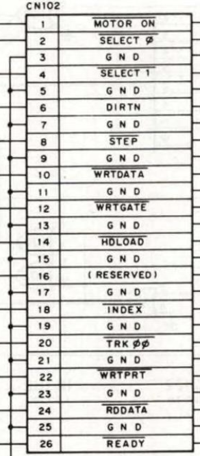
| Pin | Signal |
|---|---|
| 1 | |
| 2 | |
| 4 | |
| 6 | DIRECTION |
| 8 | |
| 10 | |
| 12 | |
| 14 | |
| 16 | Reserved (N/C) |
| 18 | |
| 20 | |
| 22 | |
| 24 | |
| 26 |
All odd pins 3-25 are grounds.
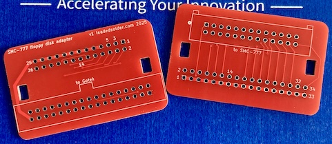
I put a 26-pin and a 34-pin connector on a KiCad schematic, and then started wiring up the pins by convention. There were some mysterious pins, such as pin 5, CHG RST, which were only in one of the pinouts, and that the Gotek didn’t seem to have an equivalent connection for. I just left those unpopulated for now, so that I could wire them up later if I had to.
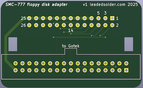
After some quick wireup, I ended up with this somewhat unusual-looking adapter PCB. My hope here was that I would put a female 34-pin connector on and have the PCB ride on the back of the Gotek for a nice compact setup. Since I still had to figure out a mount and a bezel for the Gotek, I didn’t want to have a giant PCB sticking out the back that could limit my options for placement.
I had initially assumed that a female 34-pin connector was easy to get, but it turns out it’s one of those things that is easy to get but expensive. Digi-Key had a bunch of connectors on offer, but the cheapest one was eight dollars.
Brother AliExpress helped me out with what seemed at first to be a much cheaper option. When it arrived it wasn’t the right connector at all. I was refunded instantly, and went to go buy the same thing from eBay.
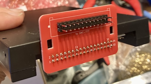
I can’t put into words how satisfying it was that this fit perfectly. That PCB is flush right against the back of the Gotek case, which I didn’t even plan for, as we’re not keeping the case.
Unfortunately, not all was well in Fit Town, the town where things have to fit properly. The 4-pin Berg-like power connector on the Gotek is a little closer to the 34-pin connector than I thought, so it’s a bit of a tight fit. I made the PCB slightly narrower for the second revision, which is the one in the repo now. I also flipped over the 26-pin connector, even though it’s a nastier route, so I wouldn’t have to twist up the cable inside the SMC-777’s case.
As I’m nearing the end of the massive pile of Goteks I bought back in 2019, I noticed that this one didn’t even have FlashFloppy loaded onto it. I went ahead and fixed that, using a USB-USB cable, a DFU utility, and some Dupont jumper leads.
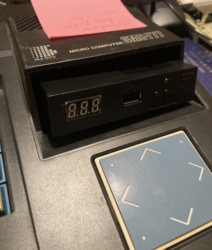
For now, I mounted the Gotek loose inside the case, sticking out the hole in the front. Since the ribbon cable is upside down, it prevents me from pushing the Gotek all the way back to be flush with the hole. This is as good as it’ll be for now, which is fine. Even if it did fit perfectly flush, there’d still be a giant hole in the bezel as the original Sony floppy drive was much taller than this one.
I only had one disk image to hand in an appropriate format, a copy of Hudson Soft’s Yakyuu-Kyou that was thankfully dumped by a Gaming Alexandria member, TurboMajikon. Thank you, TurboMajikon.
The scanned manual doesn’t even mention the SMC-777! Oh, the indignity. To be relegated to… sixth place, behind even the PC-6001mkII in Hudson’s eyes.
I converted the disk image of Yakyuu-Kyou from D88 to HFE and threw it on my USB stick. More on the format struggles later, but one disk image is really all I need to test my Gotek apparatus. So let’s do that now…
The SMC-777 happily started up and, after a reset to get past the Display Error screen, landed me on a black screen with a blinking white cursor. No “please insert disk,” no drive access, no nothing. This kind of thing usually means I have to write a FlashFloppy config file to force it to make the signals that the SMC-777 wants.
My “usual” settings (Shugart, on pin 34) are a good place to start, so I threw those into the FF.CFG configuration file on the root of the USB stick.
I also always forget to change the drive-select jumper on new Goteks from the default S1 to the S0, so I went ahead and did that too. Nothing changed.
You guessed it - classic pinout error. I had flipped the 26-pin connector twice, so I had my pins completely wrong. If I had just triple-checked the cable one more time before ordering the board, this would not have been a problem at all. I considered a bunch of fun bodges to make this work, but the board is so tightly packed, and so cheap, that I just ordered another one.
Gotek adapter, version two
When the new, rewired, version of the PCB arrived, I tried to transfer the old 34-pin female connector to the new board. Unfortunately, I accidentally mangled one of the pins when removing it from the board. Such is life, but I felt very dumb because I had waited months for these connectors. I decided to move on, and use another one to make a whole new board.
This new board acted a little differently: now I got a beep and DISK ERROR after a few minutes of not doing anything. So something is going on here.
I tried changing the “pin 34” configuration to nrdy, which is, a little confusingly, an active-_high_ ready signal. This made the SMC-777 instead produce the familiar error: Please insert DISK. So pin 34 should be rdy for sure, and it sounded like the ‘ready’ signal is getting through to the computer.
I tweaked a few other FF.CFG options, but nothing made a change. Because of the LED being lit constantly on the Gotek, I began to wonder if maybe I had wired something wrong after all.
I was just about to start looking at the SMC-777 BIOS to see what constituted a “disk error,” when I decided it was probably going to be some generic error message based on some FDC register’s “error” bit. They don’t usually have a lot of room in their software interface for verbosity. I re-checked the wiring on both ends (discovering a spider nest under the 26-pin cable!) and came up with nothing.
When doing some more searching, I found across this tweet by @superturboz, which mentions that the SMC-777 floppy drive runs at 600 rpm.
If you convert a DOS/V FDD to 600 rpm, it can serve as a replacement drive for the SMC-777, although it will not be as reliable.
Was that part of my problem? I used the HxC utility to change the RPM of a converted-from-d88 disk image to 600, but it didn’t make a difference to DISK ERROR.
While I was looking again through my disk images, I came across a raw image. SMC70CPM.IMG (md5 c712e85bec24029cd487c6ae68b4f784) seemed like it would be a good target, so I quickly defined a custom IMG.CFG entry for it. FlashFloppy has a lot of tools for telling it how to deal with wacky-formatted “raw” images – IMG.CFG is nearly as powerful as the CP/M diskdefs file.
[::286720]
cyls=70
heads=1
step=1
secs=16
bps=256
rpm=600
I fired up the SMC-777 once more, and… paydirt! We now had a working CP/M disk.
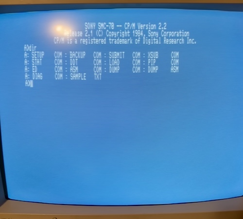
Was it useful? That’s for another day. I was psyched to have gotten this far, and went to bed.
Fiddling with CP/M
The SMC-70 CP/M disk that I had is somewhat limited, but includes some long text files, an assembler, and a DIAG utility. I ran the DIAG utility and – hoping that it would give me more confirmation as to my diagnosis – asked it for a memory check. It responded by telling me there was a “video memory error.” Thanks, I already know that.
The “CRT check,” which cycles through a rainbow of bitmaps, text colours, etc seemed to run fine, although I didn’t have a known-good machine or service manual to use as a reference to know what is normal.
I noticed that the lowercase t was still looking weird on the terminal, so I still felt confident it was PCG RAM.
Let’s see if we can load some more software on this thing.
What really is a 1DD file?
Usually, finding a big compilation of disk images for a given 8-bit computer is really simple. There’ll already be some group like Neo-Kobe who put in the work to assemble them all, make sure they’re all in a normal emulator-friendly format, and distribute them. Unfortunately, patching together some SMC-777 disk images for the Gotek was a little bit more work than that.
The most complete (yet still extremely incomplete, missing Grayhound (sic) for one) “UnRenamed” compilation of disks was all in 1dd format, which FlashFloppy’s supported image types list does not feature. At first, I assumed these images were “flat” sector images, with no metadata, but the file sizes of the compilation I received varied from 206 kilobytes to 350 kilobytes. I reached for the HxC Floppy Emulator tool, but the latest version (2.16) didn’t know how to handle these images either. Oh boy.
Going on the assumption that the 1DD format originated from an emulator, I went hunting to see if it was documented in WinSMC, a popular emulator. Sure enough, a Windows tool named 1DDTOOL was listed. Sadly, this download of the tool did not come with source, or an explanation of the file format.
Long-time readers will remember I had a struggle with various “1DD” disk images back when I was trying to figure out the similarly single-sided NEC PC-6601SR (“Mr.PC.”) Is the SMC-777 community where the tool to dump those images came from?
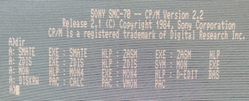
I thought I would have to write a converter. When I found a 22DISK definition, I was excited to see that it told me the disk geometry for four kinds of SMC-777 disks. Even longer-time readers will remember that I messed with 22DISK as a way to import and export files from CP/M disk images for the NEC Bungo word processor.
The MAME softlist contained a couple of IMD (ImageDisk) dumps, so at least I could use those as HxC supported that format natively. I did have to upgrade my copy of MAME before the smc777 driver properly booted those disks. But the 1DD mystery continued to gnaw at me.
Just in case, I poked the 1dd file through my d88 tools to see what it would turn up. Sure enough, it came back as a type $30 disk, aka 1D. That’s not entirely correct, as I would have expected a 70-track diskette to be a 1DD image. The utility dutifully identified that there were 70 tracks defined in the file and read out each of the 256-byte sectors of those tracks. Was this “1DD” format… just a renamed D88?
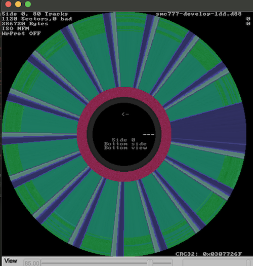
After renaming the “develop” image to a d88, HxC recognized it as a d88, but then barfed when it encountered that $30 type flag. I used my d88 tools to change it to type $40 , aka 1dd, and suddenly HxC was able to open it. This is very similar to the bodge I had to do on the “bad” dumps for the PC-6601SR, so I was finally feeling in comfortable territory.
To test my theory, I took this modified image and loaded it in MAME. It booted!

However, upon further inspection, MAME also loaded this image when it was set to a 1dd file extension, and also when the ‘type’ byte was set incorrectly. MAME is a lot less picky than the HxC utility, I guess.
Rawifying the 1DD
Now that I knew for sure these “1dd” images are really D88s, I was able to try and convert them. My target? The “raw” format that I configured FlashFloppy to use in the previous section.
Normally, I would aim for the HFE format, but I’d rather be playing games than trying to figure out how to get those into the right timing and geometry for the SMC-777.
Poring over the available dumps, I can see a few things that I need to fix:
- The SMC-777 disk format is only 70 tracks, but a large number of the dumps are 80 tracks. That’s fixable, even in IMG.CFG, but I’d rather have them be consistent.
- Some images are even double-sided.
All of these artifacts probably came from whatever non-777 computer that the original dumpers used to rip the disks. This is, again, not dissimilar to the state of PC-6601 disk images when I was starting to set up the Mr. PC.
Rather than mess with manually editing all the disk images in the HxC GUI utility, I decided to modify my d88-handling Python script to add a “dump to raw” mode2. I suspect that the HxC command-line utility would be a great way to batch-edit these images, but this way I also get an excuse to write some code.
Running this against the D88 disk image for Striz B.H., which was already thankfully in a workable format, I got a flat-file disk image of… exactly 286,720 bytes. Math works!
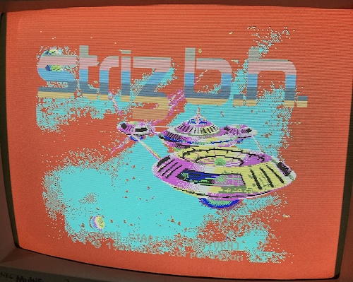
Striz B.H. booted just fine, proving that whatever it is that I’ve done is probably working. However, the colours are all screwed up. Space is not supposed to be bright red, a fact that I confirmed by looking at a longplay video of the game. Considering I haven’t fixed the video memory problem yet, it’s probably nothing to get worried about yet, but it might indicate it’s not strictly on the PCG SRAM. I find that failed SRAM and DRAM often fail in clusters, whether from shared trauma, or simply that they have a design or manufacturing flaw.
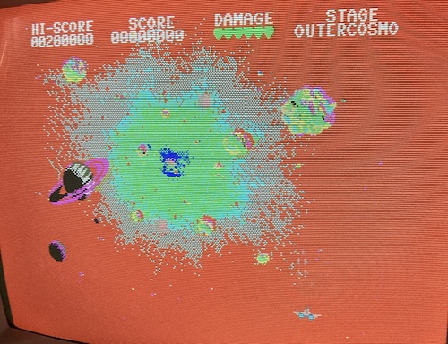
You go crush up Outer Cosmo, little ship. I’m gonna go see if I can write some Z80.
Try some more disks
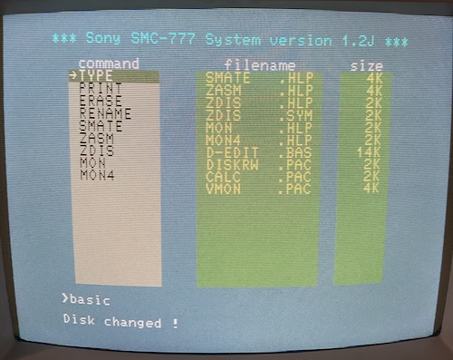
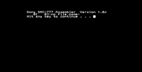
My next disk was one tantalizingly labeled “Develop.” This one boots to a “Sony SMC-777 System Version 1.4J” banner, and then tells me to “please insert disk and hit RETURN.”
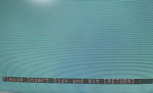
I thought this might be an indication that my adapter is not working properly – maybe the “disk change” signal really is important – but it behaves the same way on MAME. I am probably just using it wrong. For now, I booted into the SMC-70 CP/M and then listed the contents of the disk.
There seemed to be a bunch of nice programs on here. ZASM is probably an assembler – maybe even the ANN one that I was looking for – and there’s even a MON-itor. No idea what SMATE or these mysterious PAC binary files are.
The develop disk mystery
I wondered if maybe I had to boot into an SMC-777 OS disk first, and then switch to the develop disk.
Checking with MAME, I verified that I could follow this process:
- Load up the
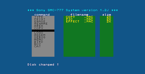
777 ORIGINAL DISK (19xx)(Sony).1dddisk image; - This produces a Sony Filer 1.2J instance;
- Swap disks to the
develop.1dddisk image; - The menu won’t change, but when you select a program from the left menu, like BASIC, the SMC-777 Filer will complain
Disk Changed!and reload the directory listing; - Load
ZASMwith impunity.
Now let’s try it on the real computer:
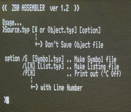
Assembler! Technically, two assemblers, assuming ZASM is different from ASSEM on the boot disk. Let’s go check that one out now:
It does appear to be different. Two assemblers!
I now had enough tools to be able to make a program that repeatedly writes to PCG memory. Then I could look at the write pins of all the mystery SRAMs, and determine from there which one is PCG. In theory, it’ll be the one whose write pin is oscillating.
Disk Driven
I’m going to leave this entry on a high note – we got a Gotek to work, and we were able to load software on the SMC-777.
In the next part, I’m going to use what I’ve learned to figure out which 6116 handles the PCG memory, and fix it. From the looks of the colour palette problems with Striz B.H., however, I’m starting to wonder if I may have two bad 6116s.
After that’s done, it will be arts-and-crafts hour, where I try to figure out how to mount the Gotek securely inside the case and ideally make it look good. Thanks for reading!
Repair Summary
| Fault | Remedy | Caveats |
|---|---|---|
| DISPLAY ERROR on startup | Not yet fixed. | Computer continues to function when reset button is hit. |
| Some caps needed replacement. | Partially recap PSU. | There is still some audible noise on 125V, which probably means a PSU modification or step-down is necessary. |
-
It’s very likely that other characters are also affected by the bad RAM, and I got super lucky that
Please Insert DISKcontains one of them in a visible position. ↩ -
You can find this utility in my pc88-disk-tools repository.
d88.py --flatten input.1dd --output output.imgwill set you right. ↩