Cleaning up after a Camel
Tags: computer sega sg1000 sc3000 soggy1000 homemade-software retrochallenge sound retrochallenge-october-2026
Now that my port of CamelForth-80 to the Sega SG-1000 is sort of working, it’s time to get it working better. There’s a lot of undone odds and ends and little bugs that I need to take care of before I can try running it on real hardware, so this week’s (abbreviated) effort was mostly along those lines.
VDP Delay
The Sega SG-1000 is designed around the Texas Instruments TMS9918A video display processor. A lot of great machines use chips in this family, including the ColecoVision, the original series of MSX, the VTech CreatiVision, the BBC Bridge Companion, and the Sord M5. In fact, it’s pretty common to see posts about the TMS99xx around these parts.
Originally, this part was designed for the TI99/4A. Being such a complex part, it does have its little foibles, and one of them is that it takes the chip awhile to “start up” before it will respond properly to commands. We saw this problem back when I was building the Sega SG-1000 RAM test cartridge, where we found that if I started doing stuff as soon as the Z80 was running, some commands would get dropped or otherwise ignored.
All of the original Sega games seem to include some variant of a wait. They either stall explicitly with a “busy loop” for many seconds to wait for the chip to come awake, or spend the free time doing a bunch of Z80 processing and setup for the main game. On the ColecoVision, this isn’t as much of a problem, as the ColecoVision’s BIOS is responsible for setting up the VDP and then handing control to the game. By the time you’re running on that platform, everything is already warmed up and ready to go. The SG-1000 is not as fortunate, seeing as it lacks a BIOS entirely.
So why didn’t we have this problem before? Well, it’s because we’ve only been running this code on MAME, which doesn’t accurately simulate this aspect of the TMS9918A. By the time MAME starts, that 9918 is ready to go. For compatibility with real hardware, this is something that would need to be fixed.
For the purposes of the CamelForth-80 port, I just copied my busy-waiting code from my RAM tester:
sg1000_cold_start:
    ; The VDP gets reset at system startup, but it takes a lot
    ; longer than the CPU to be ready for action. The BIOS on the
    ; ColecoVision/MSX/etc seems to take care of this problem for games.
    ; We could do a bunch of setup stuff here, but for now we'll just spin until
    ; we think the VDP should be willing to listen to us.
#local
BusyWait:
    ld d, $3 ; girls garden used $2 x $ffff
_busywait_outer:
    ld hl, $ffff
_busywait_inner:
    dec hl
    ld a,h
    or l
    jr nz, _busywait_inner
    dec d
    jr nz, _busywait_outer
    ret
#endlocal
Now, it’s a little slower to test the code in the emulator, but it should be more stable on the real SG-1000. How are we going to get it onto the real SG-1000? We’ll get to that in a second.
Bad characters hanging around
One of the more distinctive aspects of my port so far is that every completed command seems to end up with one of these ugly blank characters being displayed:
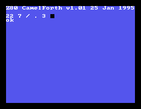
Obviously, this is something that EMIT isn’t filtering out. There’s some non-printable character being emitted, and we just blindly print it instead of dropping it on the floor. I was feeling particularly lazy and didn’t want to read any code, so I popped it into the MAME debugger to watch what was going on with EMIT.
Turns out when I just hit the return key with nothing on the line, it first emits $20 and then $0d . $0d in ASCII is, of course, carriage return. Now that I knew this, I could go back and read the code to see who was at fault. The CR word built into CamelForth was in fact sending CR and LF to indicate they want a new line to be printed to the terminal:
;C CR      --               output newline
;   0D EMIT 0A EMIT ;
    head CR,2,CR,docolon
        dw lit,0dh,EMIT,lit,0ah,EMIT,EXIT
Rude.
In my hack to EMIT, I only handle $0a , line-feed, as making a new line1, so $0d ends up being printed to the screen. Since there’s no character defined here, it gets that blank tile.
A further quick hack to EMIT dumps the character on the floor:
_check_for_ignored_character:
    ld a, c
    cp a, $0d ; carriage return
    jr z, _emit_exit
Notice how the naming leaves it open to more ignorable characters? Yeah. That’s what we in the business call extensibility.
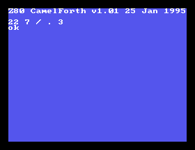
Bye, little dude.
Words that interact with hardware
I started writing some words that would be the equivalent of the Z80 OUT and IN instructions, only to find out that CamelForth already defined some. PC@ reads from a port, PC! writes to a port, and C@ and C! do the same for memory: they’re the equivalent of PEEK and POKE. This is enough to start playing with actual hardware.
To test to see if this actually worked, I grabbed the emulator, put a watchpoint on the I/O space2, and played around with it: indeed, the format {data} {port} PC! sent a byte to the I/O port I wanted.
I thought about what I wanted my first “outside world” project to be. Although the VDP would be fun to interact with directly, and bfox9900 provided some amazing TMS9918 definitions for their TI-99/4A CamelForth port, I thought that it might be too complicated for a first piece of test code.
Why not the PSG?
The SN76489 sound chip seemed like a way easier prospect: I could get it playing a tone just by sending two bytes.
I wrote some SN76489 code a long time ago, but it was mostly to just test if a bunch of AliExpress chips worked at all. It wasn’t even a good test, as I later found out at least one of them was bunk when I put it into a Soggy clone under construction.
SN76489 has two kinds of commands you can send to the chip: the “latch/data” command, and the “data” command.
Latch/data commands take:
- A header bit indicating it’s a latch/data command (1)
- A channel (tone 0, tone 1, tone 2, noise)
- A type (are you configuring volume or noise?)
- 4 bits of data
Tone is a total of 10 bits of data, so it doesn’t fit into a single byte. If you’re configuring tone, you follow that 4 bits of data with another 6 bits of data in a data command:
Data commands take:
- A header bit indicating it’s a data command (0)
- 1 unused bit
- 6 bits of data
So in other words,
| If you want to | Do this |
|---|---|
| Change volume | Send a latch/data command to any channel with type bit = 1, volume value in 4-bits of data |
| Change noise | Send a latch/data command to channel 3 with type bit = 0, noise data3 in lower 3-bits of data (1 ignored) |
| Change tone | Send a latch/data command to channels 0-2 with type bit = 0, and the first 4 bits of tone data, then a data command with the subsequent 6 bits of tone data. |
Phew, that looks pretty complicated, but there’s only really 3 kinds of operations here. Can we build these up from simple Forth words?
Fundamental operations
Doing this, of course, required me to figure out how to do some bit masking and packing. I cheated for this first bit and wrote it in assembly.
Volume word
The first word I did was PSGVOL, which sets the volume for a given channel. This one was relatively easy, once I got my pad and pen out and started tinkering with bit math by hand. Verifying it later in the debugger, I made sure that the channel number and volume data didn’t destroy any adjacent bits.
Data word
This one is very easy. I just take whatever is on the top of the stack, lop off everything except the bottom 6 bits, and send it to the PSG.
Noise word
Implementing NOISE was easy, too. First, I made a copy of PSGVOL, called PSGLATCH, whose major difference is that it did not set the volume/ bit. It latches the data in. Then, I wrote a quick Forth word which is the equivalent of:
: PSGNOISE 3 PSGLATCH ;
In other words, it would use whatever is on the top of the stack (data; the “first” argument in the call,) put 3 (the ID of the noise channel) on top of the stack, and call the PSGLATCH word to consume both numbers.
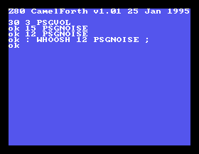
Calling that let me make rocket ship sounds, once the volume in channel 3 (noise channel) was appropriately set. Hey! Composing words is easy and fun, as long as you don’t have to do a ton of stack manipulation in the middle of ‘em.
It’s almost like this is exactly what Forth is good at: iteratively building up a working system.
Tone word
Now we’re in the most complex word of them all. Recall a few paragraphs ago: in order to send a 10-bit tone to the PSG, we first have to latch in the top 4 bits of our 10 bits (with PSGLATCH) and then send the bottom 6 bits with PSGDATA. That seems straightforward, if you have local variables and aren’t working in a language you have very little familiarity with.
I decided that I would rather do this in pure Forth, instead of writing an assembly word that called into Forth somehow. I was just too afraid of mangling the stack, and the recent success of PSGNOISE gave me some hope that I could somehow figure it out by messing around in the interpreter.
From reading the CamelForth source, I knew that 2* did an arithmetic 1-bit left shift, and LSHIFT did a logical n-bit left shift. Why these two are not the same calling convention, I am unsure, but I had some good tools to work with. OR and AND do the obvious thing as well.
First, I did the simple bitwise math to construct the bottom 4 bits of the latch command from the bottom 2 bits of the top byte and the upper 2 bits of the bottom byte. That was easy, and produced the right call, as verified in the debugger.
Unfortunately, doing all this bitwise math mangled the data argument in the process, and I’d need those bits I got rid of for the second call! It consumed the channel number, as well. I’d need to make copies of them, but how could I do it without a local variable?
The answer is stack manipulation. Forth has a bunch of cool words that do stuff like duplicate the value on top of the stack (DUP,) swap the order of the item on the top of the stack and the item one underneath it (SWOP,) rotate the order of the top three items (ROT,) and inject the item at the top of the stack beneath the item beneath it (OVER). I learned about all of this by reading the source code to CamelForth, and also the diagram on the “Stack Operations” page in the Forth Intro.
One nice aspect of Forth that I didn’t appreciate before is that the stack-modifying convention is usually specified in the comments. It’s even machine-testable in the fancier modern Forths as well. Initially, I just overlooked it as line noise, but let’s take a look and see what, for instance, ROT says it does:
ROT x1 x2 x3 -- x2 x3 x1
That seems pretty explicit! Turns out human beings write comments for other human beings to understand.
Now that I was armed with the awesome power of “finally reading the documentation,” I was ready to play around. Initially, I used a lot of paper to figure out the stack flipping operations: I suspected that I would be well-served with a Forth with some kind of stack visualizer. I ended up using Factor on my Mac to prototype the various operations.
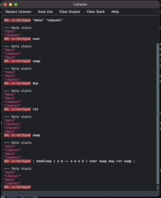
In the end, I arrived at something like this:
: DOUBLEUP OVER SWOP DUP ROT SWOP ;
: PSGTONE DOUBLEUP SWOP 6 RSHIFT SWOP PSGLATCHSET DROP SWOP 63 AND SWOP PSGDATASET ;
Wow, a non-trivial Forth program!
Clunky, isn’t it? Let’s step through what’s actually going on in PSGTONE.
- As discussed previously, I manipulate the stack to make a copy of the 2 arguments I expect to be there. The stack ends up looking like
... data channel data channel, withchannelon the top of the stack4. - I swap the order of
dataandchannelso thatdatais top of the stack, and ready for manipulation. 6 RSHIFTshifts the value ofdatasix bits to the right (remember thatdatais a 16-bit number) so the previous top four bits are now the bottom four bits.- I swap the order of
channelanddataback, so it’s in the format to callPSGLATCHSET, which sets the PSG latch with the first four bits of tone data. - I know that
PSGLATCHSETconsumed thedataandchannelon the stack, so I am now using my copies. - I do
DROPto get rid of whatever nonsensePSGLATCHSETput on the stack because I was religiously doing apop bcat the end of every call when I wrote it (I need to fix this.) - As with step 2, I swap the order of the top two items on the stack again, preparing
datato be manipulated. - I
ANDdatawith 63 ($3f ), which knocks off everything except the bottom 6 bits. This is probably unnecessary sincePSGDATASETalso does the same thing, but it makes me feel cool to have unexplained constants in the middle of my code. - As with step 4, I swap the order back so we’re ready to call
PSGDATASET. - I call
PSGDATASET, which sends a command to the PSG with the remaining six bits of data. - A tone plays.
Now, I can make really annoying ear-piercing sounds. If I knew how to play music, in theory I could compose these PSGVOL and PSGTONE calls further, making words that understand something like MML notation. However, I don’t know MML yet, so all I can do is annoying beeps.
It’s sort of annoying writing the 0, 1, and 2 in front of PSGTONE and PSGVOL all the time, so I did define some convenience words as VOLx, MUTEx, and TONEx. They do exactly what you think they do.
This can probably be way shorter. I’m sure there’s some powerful stack-manipulation word or some classic technique that I’m just not aware of yet. Also changing the order of arguments would have made things a lot easier, but I wanted to stick with the data, port convention of PC!.
Flash cartridge
I was sincerely hoping to not have to do any hardware stuff for this RetroChallenge. In the past, having to order a PCB and wait a few days for it (and the parts) has rudely thrown off my schedule. Thing is, I was starting to get tired of seeing my work running only in an emulator, and I really wanted to demonstrate the real hardware at a local meet by the end of the month.
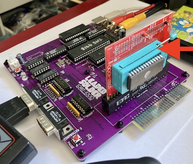
I’ve already designed cartridge PCBs for the SG-1000 before: in fact, at least two of them would be suitable for this purpose. I have a simple ROM cartridge, which holds up to a 32K program: the largest possible in the standard SG-1000 memory map.
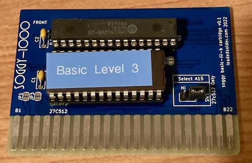
More recently, I also made a BASIC ROM cartridge, which adds a (largely unmapped and therefore unusable) 64K SRAM to the board in order to support Sega’s Level 3 BASIC.
Neither one of these is exactly what I want. For a dream Forth system, I would want these two features:
- A flashable ROM, so I could quickly assemble the interpreter on my computer and send it to the SG-1000 for testing;
- A battery-backed RAM, so the Forth system on the SG-1000 could save custom words between power-offs and resets.
Both of these problems open up a huge can of worms: at least one article worth of struggle on each. I’m not sure I’m ready to tackle them, given the few weeks left in RetroChallenge. I just wanted the dopamine hit of getting this thing to work. So I set about getting my CamelForth port ready to be placed on a standard ROM cartridge, burning it to a 32kByte 27C256 EPROM that I had lying around.
As built, my (no doubt highly wasteful) ROM was 7381 bytes, so I used my prepare.py script to pad it and then duplicate it four times to fill a full 32k ROM. The mirroring doesn’t really do anything, and may in fact even mask bugs, but I do it out of habit because it feels weird to leave part of the ROM empty.
Obviously, the iteration speed on this is a lot slower than having a dedicated flash cartridge. UV EPROMs take a long time to erase, and they’re fiddly to keep pulling in and out of sockets to program and wipe them (the legs aren’t getting any stronger with age.) At this point, though, I felt like things were “mature enough” that I hopefully wouldn’t have to do a gazillion iterations to figure out what’s wrong – I still had a pile of unerased ROMs left over from failed attempts at the RAM tester before I discovered the aforementioned “make the VDP wait” trick.
Unfortunately, this part of the project will have to wait until next week! I simply ran out of time messing with all of the sound code and the hours got away from me.
Conclusion
Wow! I wrote an actual Forth program today, with stack manipulation. Although I’m certainly not a rabid adherent to the language yet, I am starting to see the value in its very basic design.
In the next part, I’ll dig out my Soggy-1000 clone, and a keyboard, and a spare cartridge PCB, and hopefully find a ROM that I can program. Then we’ll see if this works on a real console at all. Boy, I wonder where all that stuff is in my junk pile stack?
Thanks for reading!
-
We could argue all day about whether line feed is the appropriate character for which to begin a new line on my terminal, but C on sane platforms uses
\ntoo, so I figured it was probably the right move. ↩ -
MAME’s watchpoints let you detect accesses to I/O and memory spaces. In the case of the Z80 I/O ports, you can set a non-breaking watch on anything written to port 0 with the command
wpiset 0, 1, w, 1, { printf "I/O port written!\n"; g }. Check the full MAME documentation for more details on all the cool stuff you can do even without MAME’s extensive Lua scripting support. ↩ -
The noise data consists of 1 bit, which decides if the noise is “periodic” or “white,” and the other 2 bits configure how fast the internal shifter that drives the noise runs. ↩
-
After this article went to publication, bfox9900 mentioned that it could be simplified to
: 2DUP ( a b -- a b a b) OVER OVER ;. Which is totally correct! ↩