Raising the PC-8801MH
Tags: computer nec pc88 pc8801mh batteries repair trace-repair corrosion
Hirofumi Iwasaki’s book on PC-8801FH/MH repair says that the head loading solenoid is so loud that you should be careful using the computer in an apartment at night, lest the neighbours complain. I am not hearing that, or any other noises from the floppy drives. Let’s investigate.
The NEC PC-8801MH which I got back in 2019 has been relatively unused. Most of the time, my well-equipped PC-8801SR has been getting the attention instead, and I’ve barely even touched the MH except to remove the battery from it and repair its expensive keyboard.
So why did I buy the 8801MH at all? The obvious reason is that it has high-density floppy disk drives. With these babies, I’ll be able to write high-density 5.25” floppies for the X68000.
Of course, when I went to write some X68000 floppies, the drives didn’t seem to work. I couldn’t even boot off them with a 8801mkII boot disk. The drive didn’t attempt to do anything with the disk, and I certainly didn’t hear Iwasaki-san’s loud solenoid.
My first step was cleaning. Floppy drives are filthy as hell. Unfortunately, that meant dismantling most of the machine to get at the drives, because the PC88’s power supply blocks the screws that hold in the number-one disk drive.
Case Cleaning
Did I mention the rest of the computer was also filthy?. At the start of cleaning it, I just barely touched the top of the case to a sink full of hot water, and huge black clouds came out from the accumulated loose dirt without any scrubbing on my part. Gross.
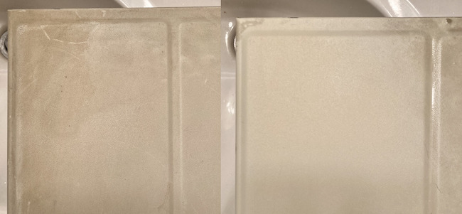
Some quick cleaning was done using a paste of Oxyclean and water with a toothbrush. This technique works well to get dirt out of the textured/powder-coated finish. The front case plastic was cleaned (gently and probably inadequately) with a Lysol wipe, while the power-supply fan was blown out with compressed air.
Next stop for the cleaning train: the drives. Choo-choo.
Drive Cleaning
The PC-8801MH uses two TEAC FD-55GFV-70 floppy drives. As far as I can tell, the “V” stands for “VFO,” or variable frequency oscillation. The party trick here, in TEACese, is that it can run at either 300 or 360 rpm to vary the density of the disk being read or written.
I wasn’t able to find any specific data sheets on this drive, but the FD-55 was used as a base for a lot of other drives. TEAC changes the letters and numbers around at the end to represent the different features and jumper configurations. For instance, lots of IBM PCs use the highly desirable FD-55GFR 1.2MB drives.
An interesting feature is that apparently pin 4 of these drives are a “double step” mode, similar to the double-step mode on the PC-6601SR, presumably to deal with 40 track (“2D”) disks in an 80 track (“2DD”) drive. For high-density, pin 2 is toggled for density select, which also changes the colour of the access LED on the front. Cool!
Once I hooked one of the drives up to the Greaseweazle, the LEDs are no longer dimly lit as they were in the PC88. Something weird is going on.
I did a quick test write-and-read with default settings before doing any cleaning, and both drives returned basically line noise:
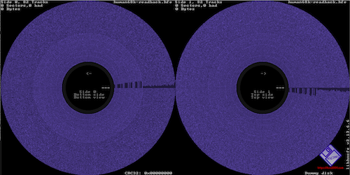
Even when reading a disk that I knew had some data on it, nothing was coming out of the drives. I did a little head cleaning and lubrication, but it didn’t change the outcome.
I could see that both of the drives had solid head stepper action and the main spindle was spinning confidently, so what was wrong?
After reading the data sheet, it was revealed that the “head load” pin needed to be activated in order to, well, place the head onto the disk. With the head just floating around in space, the drive can spin and seek all it wants, but no useful data will ever come back.
I considered making a wiring adapter to force that pin low – the Greaseweazle doesn’t have enough IOs to control it from software – and then I had a weird pit in the bottom of my stomach. What if the drives were fine?
Maybe A Different Problem
I attached a Gotek equipped with FlashFloppy, using my edge connector adapter, set to S0. I inserted a USB stick full of images that worked fine on the Goteks in the 88SR, but they wouldn’t load either. The Gotek’s light would blink for a split second on startup, but there was never any indication of a cylinder or sector change. Something was wrong with the computer, not the drives!
This also gave me a good opportunity to better understand the dual-floppy-drive mystery of the PC88s, as I did not want to buy more HxC licenses in order to run dual drives in this machine as well.
Both drives are jumpered identically, so they can be interchanged. The 88 motherboard presents different signals to each drive.
I removed the cables to buzz them out, and then saw a lot of green fuzz in the area. Death fuzz.
NiCad Strikes Again
That’s right, despite seeing battery damage bad enough to lift the silkscreen, I didn’t properly repair the board in the last entry.
The most charitable depiction of my actions is that I had assumed that I would do it some other time in the future, and… that time is now.
I also found a dead spider with a bunch of webbing and a few egg sacs in between a couple of ferrite beads going to the digital-RGB video port.
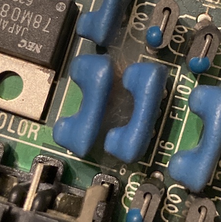
The sight of it made me sad, but there’s nothing I can do for her now. Rest in peace, little arachnid.
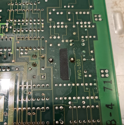
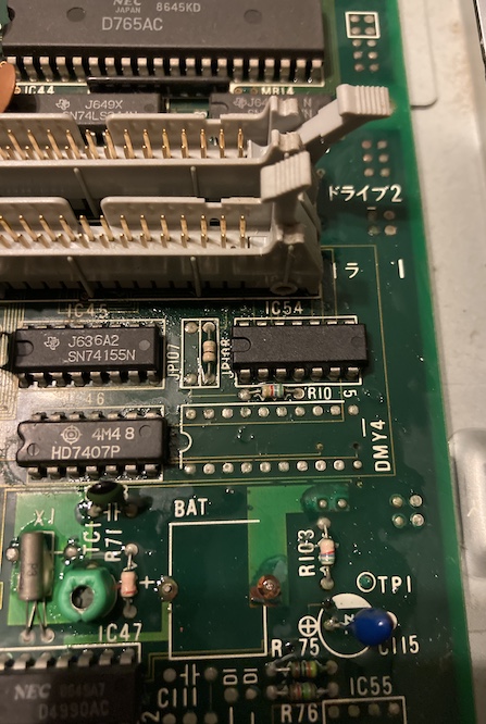
I had not removed the board previously to check on the underside; here you can clearly see that the creeping green death of oxidizing copper has ripped through onto the underside of the board through some through-holes and vias.
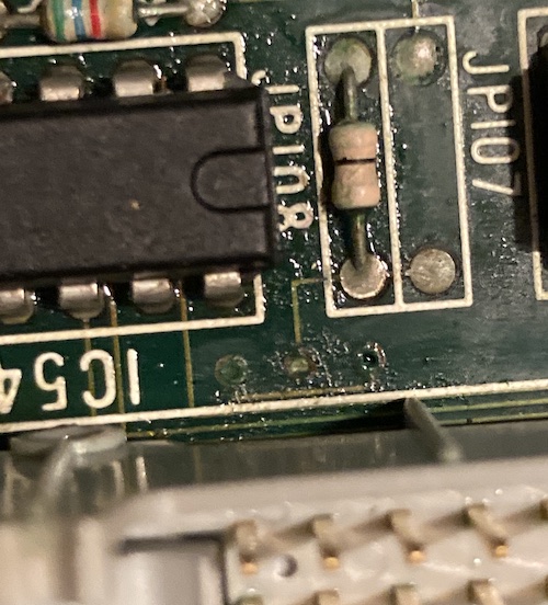
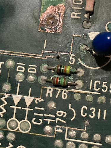
Some resistors were already starting to lose their painted-on value bands, so I took a picture of these two before I started working too hard in the area.
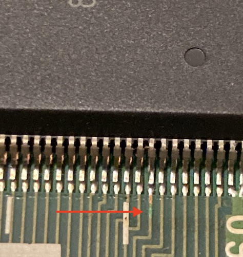
While looking over the rest of the board, I noticed that one of the legs on one of the large QFPs was reflecting the light a little weird. Upon closer inspection, the pin was slightly bent, and the solder mask on that trace was damaged. It was nowhere near the battery, though, so I made a quick continuity check, put new mask onto the exposed bit, and moved on. Maybe somebody on the assembly line dropped the board?
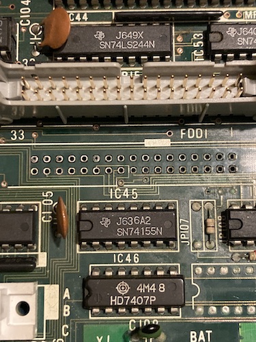
As I suspected, battery electrolyte had crept under the FDD1 connector. To clean underneath and check for dead traces and vias, it would have to come out. Luckily, it was clean underneath.
Removing the FDD connector was easy. Unfortunately, the same could not be said for the resistors and capacitors in the area, especially the 22µF tantalum capacitor at C115, which took nearly an hour to remove the severed legs from the board. A lot of battery-hardened dead solder, poor access, and big copper pours confounded me in this process.
New Side Quest: The Mystery of the 54th IC
I wanted to depop and test IC54, because it was in the battery path, close to the floppy connectors, had a lot of visible corrosion on and around it, damaged silk screen right in front, and seemed to be missing its label. But what was it?
Because of the size and shape of the package, I expected it to be a TI-branded 74 logic IC of some kind, and it seemed to connect to pin 22 (/WDATA) of the FDD1 connector. A good candidate to test when experiencing floppy problems.
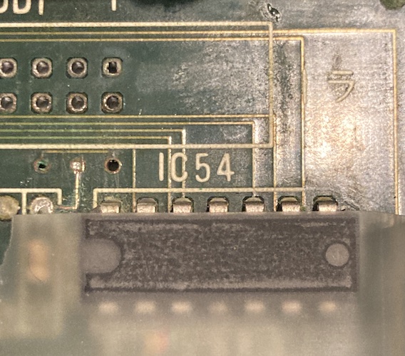
I heard that using Scotch tape on the top of a sanded-down IC can help expose the label, so I figured it might work here. Unfortunately, it did not.
In some outstanding luck, Michelle from the Doors & Dungeons podcast did a far better job Googling than me and turned up this blog about PC-8801MH floppy drive repair, where the chip is not yet fully eroded by the same leakage. It is an SN7406N inverting hex buffer!
The 7406 desoldered surprisingly easily for something that was marinating in battery sauce for awhile.
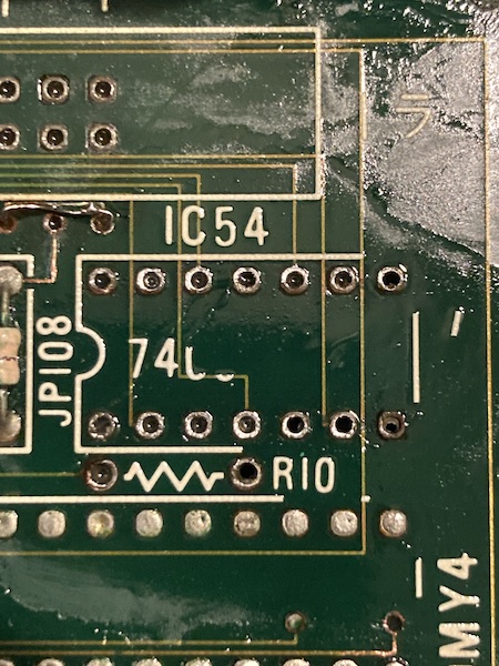
I was pleased to see that NEC even silkscreened “7406” under it, although that silkscreen was also damaged, and immediately washed away when I applied a little alcohol to clean the area. All of these top-side traces seemed to tone out, and so I went to test the 7406 using the TL866 EEPROM programmer software that I’ve used in prior entries.
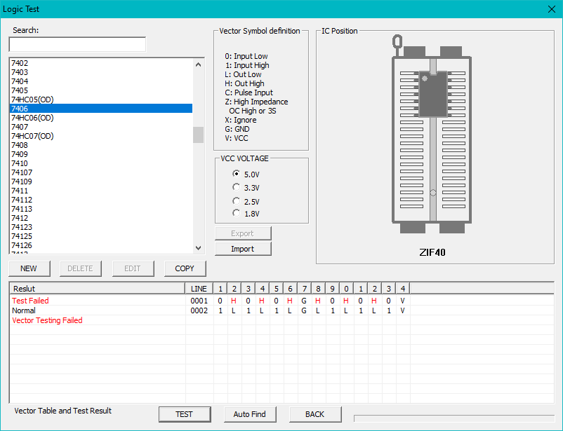
It is suspicious that all of these lines failed on just one of the tests. I figured it was much more likely that this 7406 was fine, and like the 7407 before it, the TL866 test script simply hadn’t been configured properly for an open-collector IC. It felt like those “Hs” should be “Zs.”
Changing the test script to “74HC06 (OD)” (for open drain, presumably) lets it pass. This chip is fine, and it went back into the board with a socket. I would have liked to have replaced it just to have a legible label, but with the current shortages, unfortunately it was not possible to get a new one outside of eBay. In its stead, I made a “7406” label and stuck it to the top. Hopefully, no one will ever have to replace it in the future.
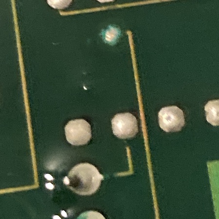
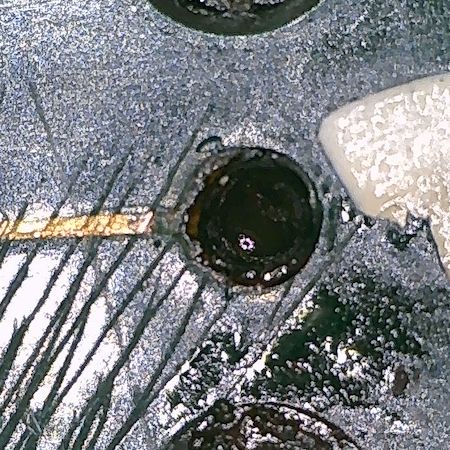
I also cleaned, scraped back, solder-plugged, and then masked over a handful of greened-up vias in the area. None of them were “bad,” but certainly it would not have been a nice thing to leave them rotting until later, when they might produce a more mysterious fault.
Here’s some microscope video of clearing out the battery electrolyte and copper corrosion from a good (for now) via with just a tiny amount of white vinegar. It’s not great, because I frantically tried to tilt the board to keep the electrolyte from leaking into a nearby resistor network, but it is some pretty cool looking footage.
Head Load
Michelle also found this other blog post by kitahei88 which briefly mentions that JP108 and JP105, both 0Ω resistors/jumpers, are connected to the head load pin of the floppy drives (JP108 to FDD1, JP105 to FDD2,) I decided I would probe those vias to ensure that the signal is getting all the way to the drive.
A continuity test passed with no voltage drop, so the jumpers, traces, and intermediate vias were good enough to work but not explain the failure. All of the corrosion was cleaned up anyway, and the traces re-tinned before being sealed up.
Interrupt, Interrupted
I kept moving my way backward from the floppy connector towards the battery leak epicentre, and found a bad via near the aforementioned hard-to-remove tantalum capacitor at C115.
To patch a via, I scrape back the traces on both sides of the board to expose the copper. Then, I clean the area, apply a ton of paste flux, tin the traces, and run magnet wire through the via to make contact with the newly-exposed traces on each side.
After patching the via, I realized that it was a trace for (among other signals) pin 18 of the µPD765 floppy controller, which is INT. Seems like a pretty important pin – this snaking trace had also failed on one of the Japanese repair blogs.
The via and the repair wire (0.2mm enameled magnet wire) were sealed in with some cheap AliExpress solder mask.
The Resistance Is Here
Eventually, I decided that I had probably removed enough of the affected parts, and started to stick in new passives. The resistors had sucked in a lot of green death, but they still seemed to be functioning. It was easy and cheap to replace them, although the new 1/2W resistors look a little silly compared to the old 1/8W ones.
The value of R75 was a puzzle, because the colour bands fell off of it. When desoldering it, it also dropped into the carpet of my workshop, so I couldn’t measure the value exactly. Good thing I took the picture above as well as this one in the previous entry, where luckily the colour bands were still intact.
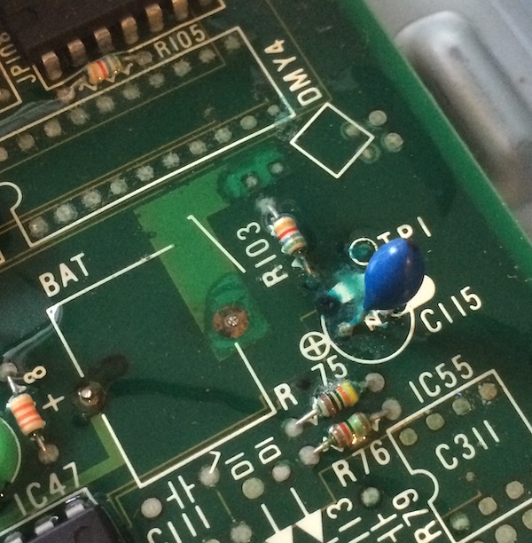
After a quick buzz test, it wasn’t immediately clear to me exactly what part of the circuit R75/R76 are involved in, so they may not have been needed at all once the battery is removed. R75 seems to be a +5V pull-up, but I couldn’t figure out where the other pin of it runs to, without any visible traces.
Do The Floppy Flop
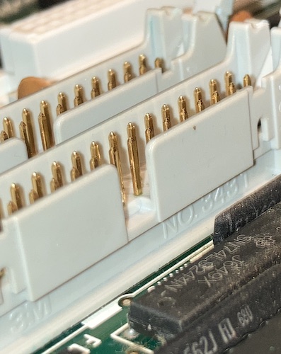
One small disaster – I accidentally pushed out the #2 pin in the floppy connector while trying to hold it in place for soldering without lining all the pins up properly. Just an inexcusable rush job on my part. After a few attempts at repair, I gave up and ordered a replacement connector on Digi-Key.
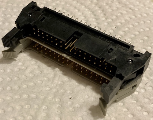
The replacement 3M N3431-6303RB did indeed seem to be the right part. It had a solid retention of the floppy cable. The part itself looked about the same, except that it was black, and the little latchy claws didn’t have the nice curved thumb-pads on the end.
I also took the time to tin and then clear all the through-holes on the connector to make sure it went in smoothly. An annoying (and expensive) setback, but at least a replacement part could still be obtained.
Test Fire One
I put the board back in the case and plugged in a Gotek. On the screen, I could see that tracks were being read! However, the 88MH refused to boot off the only image I had (a copy of The Black Onyx) which may well have been a FlashFloppy configuration.
Blog superfriend sampson sent along a known-good N88 Disk BASIC disk, so I plugged it into the original floppy drive, wired the drive up, and then booted the computer. True to Iwasaki-san’s promise, the disk head load solenoid was so loud and sharp, I nearly dropped the drive when it came up in surprise.
The noise is similar to that of an Apple II disk drive trying to find track zero, but much louder since it’s metal-on-metal inside a metal case. You know you’re really computing now.
![The sign-on message for N88 Disk BASIC. It says: "Disk version [Oct 20,1986]"](/assets/pc8801mh-disk-basic-booting.jpg)
And sure enough, after a bit of quick seeking and machine-gun head loading, the N88 Disk BASIC was booted!
Putting the machine back together was relatively straightforward: coarse thread goes into plastic, fine thread goes into metal. It was aided by the fact that, even after cleaning, you could still see the “shadow” of the fasteners on the metal internals in order to figure out if there was a washer or not.
Conclusion
I wouldn’t say I was happy to finally sling a soldering iron at one of my PC-8801s, but the act of communing with it made it feel more like the MH belongs to me. Mostly, I’m really glad that the damage could be reversed, and I now appear to have a PC-88 with a pair of working high-density 5.25” floppy drives.
Repair Summary
| Fault | Remedy | Caveats |
|---|---|---|
| Diskette inserted into drive #1 is not read. | Repair broken via near C115 (INT signal for FDC) | |
| Some idiot broke a pin on my #1 floppy port | Replace it with a new part |