Amped Up For Artdink (Travelling to Tokio, Part 1)
Tags: computer nec pc98 pc9801 pc9801ra2 power-supply floppy 3d-printing repair artdink
Despite not being able to understand more than preschool-level written Japanese, I decided to get in on the “importing games from Japan” craze. Of course, I jumped in at the deep end and decided to pick up an Artdink-made city simulator with lots of cultural and regional in-jokes. Also, the city is in space. Did I mention that my PC-9821Ap2 can’t run it?
What is Tokio?
Tokio is an Artdink1 simulation game from late 1992. More than just a city builder like SimCity, it is concerned also with municipal politics. Constituents and pressure groups meet with you, you have to worry about public opinion polls and the rumblings of internal party factions, you must campaign to get re-elected, and you vote on ordinances and set tax policy to make sure you don’t go bankrupt or kill everyone.
The real spice comes from two aspects:
- All of your constituents are weird comedy figures (some would say stereotypes;)
- You’re in outer space.
The framing of the game is that the Tokyo metropolitan government, sick of having nowhere on Earth to expand, puts up a space station, “Tokio,” and declares it the 24th ward of Tokyo. So on top of the usual city-management, electoral campaigning, and government-policy stuff, you also have to set space shuttle schedules (it is an Artdink game, after all,) manage oxygen, fly people to the moon, and buy supplies. The whole thing is an utterly strange mixture; take a look at the Project EGG trailer for the game to see it in action.
This game was apparently met with some reasonable success in the market, enough to produce a sequel and a re-release for IBM PC Windows, and its music even ended up on the Artdink 10th anniversary soundtrack compilation in ‘96.
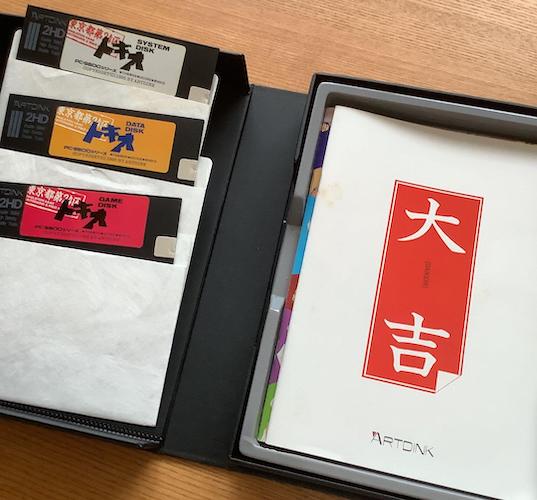
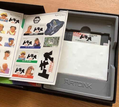
I bought this boxed copy off of Mercari for ¥2100, which is a nice discount over the ¥12,800 price listed on the box’s spine. There were lots of cheaper copies floating around, but they had smoking damage, or missing manuals. This one even had the user (save) disk stickers:
I’ve avoided buying used PC games from Japan for a few reasons. Mostly it’s the fear of mouldy disks, but also because Artdink won’t see a single red cent from me buying a used copy of their game 30 years after release.
The more observant among you may notice something about these pictures. Those are 5.25” floppy disks, and I don’t have a PC-98 with a 5.25” drive. Oh no. I have to buy another computer?? What a shame.
Buying Another Computer
The back of the box says that you don’t need much horsepower to run Tokio. Anything that’s a PC-9801VX or better can run it, but I figured as long as I was in the market I would try to find something good.
Of course, this means navigating NEC’s alphabet soup names. After some consulting of different spec sheets, I arrived at this rough mental model of the naming scheme in this time period.
| Machine tier | Suffix | Example |
|---|---|---|
| Budget | X | 9801RX (286) |
| Midrange | S | 9801RS (386SX) |
| High-end | A | 9801RA (386DX) |
One of the nice things about the confusing pile of PC-98 models is that, with so many different search terms, you’re virtually guaranteed to be able to find a model that is relatively unknown and thus affordable.
I decided that I would probably want at least a 386SX to run this game, so I started looking for a PC-9801RA, PC-9801RS, PC-9801ES, PC-9801DA, PC-9801DS, PC-9801FS, or PC-9801FX. If the stars aligned, a 486-powered PC-9801FA/BA/BS/BX would be even better, but I figured those would be vastly uncommon and command huge prices especially with a 5.25” drive, so I set my sights a little lower and targeted the RA models. I also avoided “/U” models as they were listed as having 3.5” floppy drives, which is a bit of a shame, as some of those were dirty cheap and in nice shape.
Much to my surprise, I found that there were a lot of PC-9801RAs for sale. There were two versions of this machine, much like with the PC-9801UV: a PC-9801RA (1988) and a PC-9801RA21 (1989) which even had built-in SCSI. The RA seems to have been a bit of a big deal when it came out, as there is a lot of glowing praise for this specific model. There were also a ton of RX models in near-pristine condition; clearly sales were strong right at the edge of the Bubble Era’s collapse, as only a few years prior, in 1986, the PC-88 still outsold the 16-bit NEC computers.
I did a couple low-ball bids to feel out the market, and I was delighted with the results. Although I lost all of my initial snipe bids, I was losing by fewer than ¥500 each time, which meant that there was likely only one or two other competitors willing to outbid me on these machines. Since I was in no hurry, I kept plugging away slowly at Yahoo Auctions’ stock of RA/RA21s. Mysteriously, 286-powered PC-9801RX models seemed to have been listed for much more than the RAs.
Epson of a…
This is as good a place as any to talk about the Epson PC-98 clones. They are, well, clones of NEC PC-98 machines.

Just like with IBM PCs, NEC had a group of mean old computer engineers rip off their systems and try to break up their hardware monopoly, chipping into their eyewateringly high margins. Unlike IBM, however, NEC was generally successful at discouraging clones. Despite other attempts, Epson was the only big cloner, and NEC managed to harass them with enough patent lawsuits (you can’t have a DIP-switch configuration screen, that’s our idea) and tricky hidden software protection that they seem to have eventually just given up.
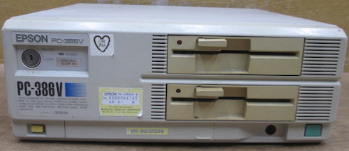
Some of the scars of this battle can be seen in this machine. I bought this Epson PC-386V-STD for ¥3000, with no other bidders – you’ll see why in a second. I went looking for it because it was listed under the “compatible models” section of the Tokio box.
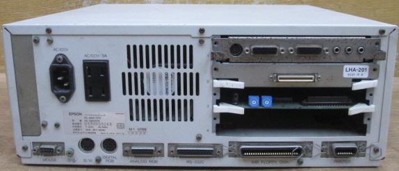
This particular machine was loaded with an LHA-201 SCSI card, and a Sound Blaster, of all things, which made the proposition even sweeter. The Epsons also have semi-proprietary 5.25” floppy drives, so having a dual-disk system gave me twice as many chances that I’d have a working floppy drive.
What Artdink didn’t tell me, however, is that this Epson machine doesn’t support EGC. EGC, or Enhanced Graphics Controller, is the grandchild of the classic PC98 graphics system, GDC (Graphic Display Controller.) It offers blitting acceleration for the PC98’s planar framebuffers, implemented using custom logic… that NEC was not going to let those jerks at Epson have.
Tokio would run on this Epson, alright, but a lot of games and other software expected EGC. It also doesn’t have a YM2203. One day, it would be nice to have a “real” 5.25” PC-98 with it. If only someone forgot to cancel his snipe bids…
Hatch That EGC
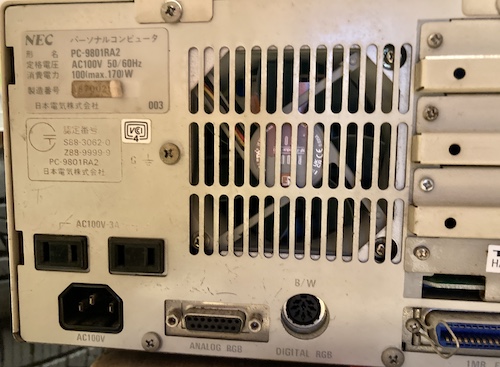
And that’s how I won a ¥5000 PC-9801RA2. I was once again the only bidder (gulp) but there’s a good reason for that: the disk drives reportedly don’t physically let you shove in a floppy disk. I can fix mechanical problems all day long, I told myself, and the drives used in these 98s have a silly “head protector” that comes unglued from the load arm and falls into the mechanism after a few years.
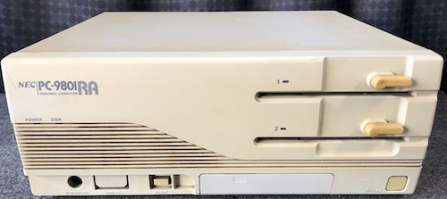
This machine was shown as booting, at least, although it had nothing special. It’s a stock 386DX/16, with 1.6MB of RAM, no FM sound of any kind, and a SCSI card with no hard drive attached. This is a good example of the NEC tax hard at work: ¥2000 more for a machine with fewer goodies.
Fix The RA2
Because of the cost of shipping, I could only choose one of these machines to come over first. The one I decided to bring in was the PC-9801RA2. While I love the Epson’s middle finger to NEC, I just wasn’t sure if I would have a great experience without EGC.
Of course, I forgot to include my new copy of Tokio in the box, so the PC-9801RA2 arrived without anything to play on it. Nobody said I was smart.
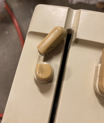
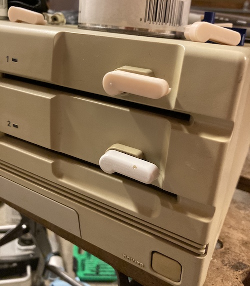
The yellowed and cracked floppy lever did not survive shipping. Luckily, not too much of it broke off, and it got caught in the bubble wrap. So at least I still had my favourite game to play: fixing old broken computers.
Opening the RA2
I didn’t have any luck pulling the lever off the front, so I figured that I had to take the computer apart and work an e-clip or something off from the back.
What I found inside the computer was: battery damage.
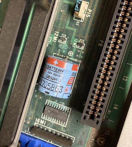
Ugh. I clipped it out, cleaned it up, and was impressed at how nice the joints and vias looked afterward. It will still need to be reflowed and buzzed out, as I suspect the serial port may not be very happy anymore.
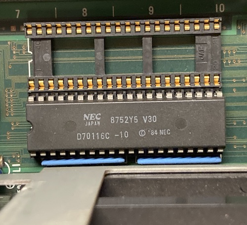
North of the battery zone is this pair of sockets for an NEC V30 and most likely a floating-point coprocessor for the same. In legacy (“slow”) mode, this computer will switch off the hyperfast 386DX/16, and turn on this V30 instead. That’s very cool, and goes to show you what kind of fun things you can do with the BOM cost, when the company that makes the chips also makes the computer.
The 386DX did not have a coprocessor either, and was the original 16MHz part. Too bad: I was hoping for a freebie clock bump at least.
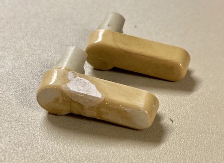
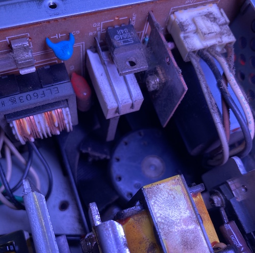
Next to the floppy drive cage, I found the culprit for the seller’s complaint about the drives. The reason they couldn’t insert diskettes is probably because of these “head protectors,” which are little metal shields intended to keep crap and debris away from the sensitive read heads when they fall into the hole.
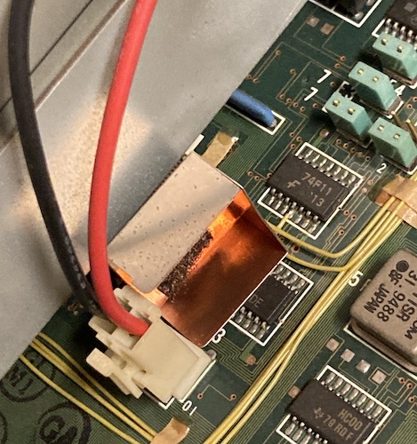
They’re glued onto the back of the uppermost head arm through a piece of foam, and the foam seems to dry out and fall apart over time, causing the shield to fall into the drive. If you’re using a disk at the time? You’re not going to have a good day. I found a loose one in the topmost drive (“Drive 1”) and this one on the motherboard, which had presumably been ejected from Drive 2.
At this point, I realized you couldn’t remove the drive without removing the plastic levers first. The plastic levers I came in here to remove in the first place. Reaching around the front, I was able to pull off the lever on the lowermost drive without much effort. That was not the case for the broken-off one, I can tell you that much.
It took about an hour of wrestling with the broken stub to be able to pull it off the “D” shaft holding it onto the floppy drive. I ended up soaking it in Seafoam Deep Creep, and then working it loose with a succession of plastic trim-removal wedges. It made a real bad sound every single time it moved.
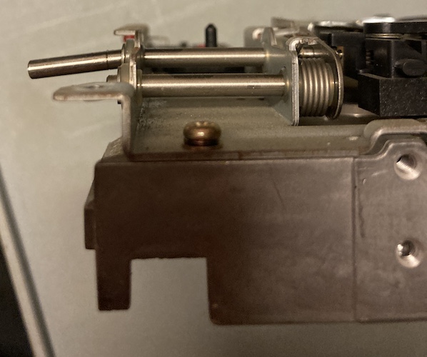
The reason for that awful screeching noise? Simple – the shaft on the end of the eject lever cam was badly bent, causing the shaft to bind up on the front of the case. A date with my Knipex water-pump pliers made this mostly straight. I removed the head protector from inside this drive, where it was rattling around near the lower head.
Because I figured the top-most drive had seen the most wear over the years, I rotated them – placing the old “Drive 2” in the top-most slot. Of course, I remembered to change the “drive select” jumpers on the back, so that they would work as expected. This isn’t my first rodeo.
As an aside, the SCSI card was missing its eject levers – probably broken off long ago. This meant it was a huge bear to get in and out of the C-Bus cage, but I ultimately triumphed.
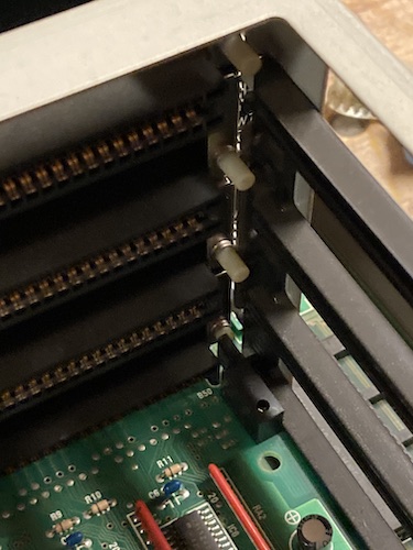
These little buttons in the C-Bus slot toggle the slot’s address bus width between “20-bit” and “24-bit” (pressed) modes. As such, this SCSI card has a little plastic finger stuck on the end of it to push the button for its slot. Simple and effective.
Fixing the Lever
To fix the more broken of the two floppy levers, I used two-part epoxy. This made a bit of a mess, as it always does, but after some clean-up, sanding, and filing, it left a strongly bonded part that sort of had the profile of the original.
Although the second eject lever was not broken, it had a pretty dramatic stress crack on the outside that was probably going to break eventually. I packed the voids on the backside of the lever with more epoxy, to give it some reinforcement.
Despite my better judgment, I decided that I would try to paint the eject levers, to make them look a little nicer. Looking through my auto body paint supplies, I found an old can of adhesion promoter and an even older can of white appliance epoxy. The latter didn’t say I couldn’t spray it on plastic, so after the requisite 24-hour waiting period for epoxy harness, I cleaned the parts thoroughly with grease and wax remover to prepare them for paint, then coated them with a thin film of adhesion promoter to help the paint stick to the plastic.
To check for colour match, I spraypainted a chunk of plastic I had lying around, and the can of appliance epoxy failed on the very first pass, turning into a sputtering mess that got everywhere. I threw it in the bin and grabbed an equally-old can of white Tremclad instead, which did an okay job, but was very far from the colour of the RA2’s faceplate.
After sanding away the runs in the paint and doing a very light touch-up coat, the levers were ready for re-installation. Not my best paint job ever – all the minute flaws in my sanding and filing showed up very, very clearly with the new colour – but it looks better than it did.
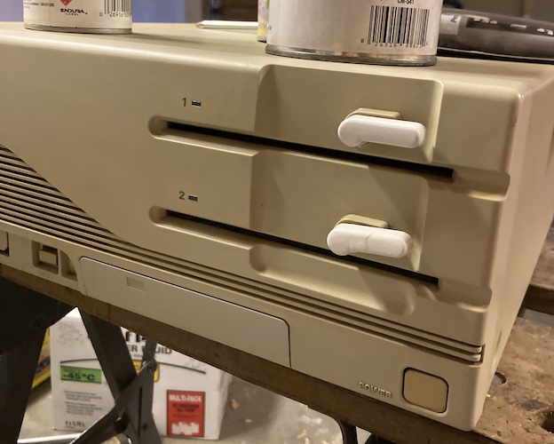
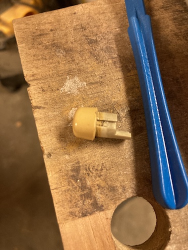
Unfortunately, as soon as I popped the repaired one onto the shaft, the brittle plastic crumbled just past my epoxy repair. What a kick in the teeth!
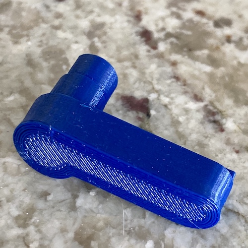
Angry, I did what I always do when confronted with old garbage that is too expensive to replace: clone it. I took the surviving lever and made a bunch of measurements of it with my kinda-trusty digital caliper, then popped it into Tinkercad for an afternoon of squinting and frustration. You wouldn’t think something like this would be complex, but there are a lot of subtle flares in the design. Mine is a lot cruder, but you know what? It’s not a pile of dust on my garage floor, either.
The first version kind of, sort of worked. If I drilled out the hole to 5/32” and really slammed it on, it would fit and actuate the drive’s carriage-load cam with no problems. However, the homemade lever’s handle was too long to clear the front fascia of the case, so a version two was necessary.
My friend keegs was printing these off for me and graciously dropping them off in my mailbox whenever he drove past my house, so iteration speed was not especially fast. I’m extremely grateful to have this option available at all, as maintaining a 3D printer seems like a fiddly, thankless hobby in and of itself.
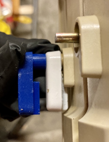
Version 2 fit a lot better, although I still needed to slide a 5/32” drill bit into the hole to make it fit. The “stopper” tang once again broke right off. Without the little tabs in the hole, the lever wouldn’t return fully to horizontal position when the D-shaped shaft of the floppy drive did, either. However, it looked right, and more importantly, it worked right. I started making some changes for version 3, but I finally had a working floppy lever.
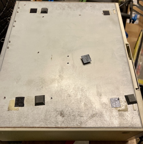
While I was “in there,” I also used two-sided Gorilla Tape to stick the rubber feet back onto the bottom of the case after cleaning off most of the accumulated filth from the exterior with a generous dose of Spray Nine multi-surface cleaner. I am actually amazed that all four of those feet survived, considering how far they migrated over the years. One of them fell off while I was working on the machine, which is what prompted the repair.
Let’s move on to… building some hardware. What? I thought this was going to be one of those entries where I just play a videogame.
Power Supply
Even though my PC-9801RA2 was sold as working, I decided it would be a good idea to put in a different power supply, so I could set up the computer away from the step-down transformer without worries.
On top of that, I had been warned that the Sanken PU-463 supply built into the PC-9801RA2 is somewhat unreliable. In fact, it’s so crappy, that blog friend Ethylene in China had developed a replacement board using a PicoPSU, similar to the mattsoft X68000 ACE PSU and my own X68000 PRO PSU boards.
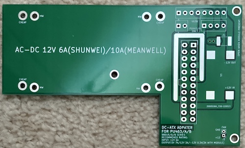
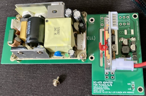
This new board, the PU463-ATX, accepts a 3”x2” 12V supply and a PicoPSU, and uses the PicoPSU to generate all the voltages required to keep a PC-9801RA2 happy. I traded some Leako and Soggy boards to blog superfriend CDP1802 in exchange for one of his PU463-ATX spares.
This part of the project took awhile, as sourcing is wont to do these days. I ran into a lot of shortages here.
The Mornsun Also Rises
Although I already had a (clone) PicoPSU on hand, the Meanwell EPS-65S-12 3”x2” 12V supply I wanted to use was out of stock – with no restock expected for months. Luckily for me, I saw a tweet by Leon Kiriliuk about PSUs made by a company called Mornsun.
Mornsun, a manufacturer also located in China, makes 3”x2” single-voltage power supplies of a similar design to the Meanwell product. Except they’re actually in stock, and you can buy them. The mounting holes are the same as the Meanwell EPS-65S-12, and so are the JST VH connectors, which makes me wonder if there is some kind of power-supply mounting standard that the English datasheet didn’t name. Still, I’m not one to look a gift horse in the mouth, so I picked up one of their supplies – a 65-watt LO65-10B12 – from Digi-Key.
This supply looks almost identical to the Meanwell one, except there’s a lot more silastic goop, and the “primary side” uses different components for protection. Maybe the weird mounting tab in the foreground is part of the standard, as it exists on the Meanwell as well.
Following Ethylene’s quality assembly instructions, I mounted the Mornsun converter to the new PCB on M3x8mm standoffs. Since screws were going in at both ends, I wanted to make sure that it wouldn’t rattle itself loose, so I used blue Loctite on the mounting screws which held the standoffs against the board.
There is one screw hole under the converter which mounts the PCB to the power-supply case, so I used Loctite on this as well, as it would be inaccessible with the converter installed.
This Is Giving Me Mini-Fits, Junior
When I did the X68000 PRO PSU adapter board, Digi-Key was plumb out of 20-pin ATX connectors. Since the PicoPSU is a 20-pin connector, I was smart enough to specify a 24-pin connector on the new board. This way, I could use whichever kind I could source.
Ethylene has done the same here, which I’m very grateful for. Why? Because this time, the 24-pin ATX connectors are the ones that are out of stock.
In order to try and find this connector, I ordered some 24-pin ATX connectors from AliExpress, and while the “female” side of this new connector mates fine with the PicoPSU clone… the male side’s row spacing is too narrow to fit into the motherboard.
This AliExpress connector only has a 4.2mm row spacing between pins on the board side, whereas the “real deal” Molex 5566 datasheet says it has a 5.5mm spacing. Weird – and frustrating. I’m sure it could be bodged, but I’d rather not do that in a high-current environment like a PC power supply. I’m not sure where this knockoff connector is supposed to be used, but I suspect it’s meant for a wiring harness and not installation into a PCB.
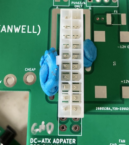
I ended up paying $5 per connector for a 20-pin one from Digi-Key, because at least those ones were finally back in stock. I’m a little worried about how hard it is becoming to get these very commonly used connectors; pretty soon I’ll be pulling them off of scrap PCBs. At least I know I can change to the “wrong” 4.2mm footprint now, because I have a lot of connectors on hand to use with it.
Twelve Below
The original PU-463 supply generated -12V, which is a problem for a modern tiny PSU like the clone PicoPSU. To fix this, Ethylene used a common “negative voltage generator” module, and provided a Taobao link. Rather than try to figure out how to order from Taobao (although the very cheap prices are tempting) I picked one up from AliExpress based on the highly scientific method of “it kinda looks like the same one.”
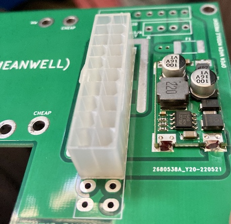
The board can use either the -12V rail from the ATX power supply (by installing a fuse or jumper to close the “F1” footprint) or one of these little generator boards, which are fed off of +12V. It seems a lot beefier than the -5V voltage inverting charge pump that I used on the Leako!
You Sanken My Battleship
I was lucky to have a PU463 supply in this computer, as opposed to a PU463A, because the latter needed a little bit of bodging to work with this board. A revised board has since been made to allow for the “A” harnesses, but I already had this one.
Opening this supply was not exactly easy. I removed what I thought were all of the screws, and then had to wiggle my fingers inside in order to remove the DC wiring loom’s grommet and pull it out a slot in the side. Only then did I realize that I could have unscrewed and slid out the top of the PSU instead, which would have given easy access to all the connectors. Oh well.
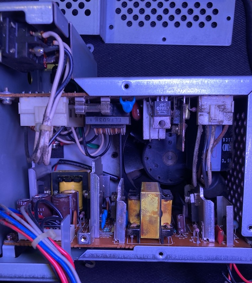
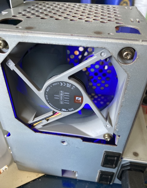
Lots of gross gunk had been pulled through the fan over the years, accumulating in the corners where it was hard to get at with a toothbrush.
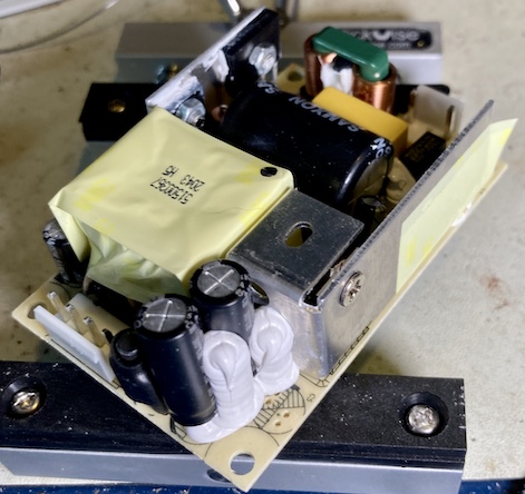
As you can see from the pictures, the original Sanken power supply consists of two PCBs. One (“primary”) is mounted on the top and accepts/switches/rectifies the mains power, and the other (“secondary”) seems to do all the regulation to supply the DC voltages for the computer itself. When this is installed in the computer, the power plug is at the bottom of the machine, and the rest of it sort of hovers above the motherboard, bolted into the side of the card cage.
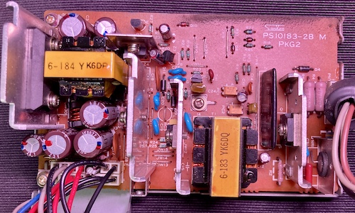
Both boards in this power supply are, of course, nasty. Yuck!
Unable to clean it effectively, I threw the original fan into the “old PSU parts” bin and sourced a $10 Noctua NF-R8 80mm fan to replace it with.
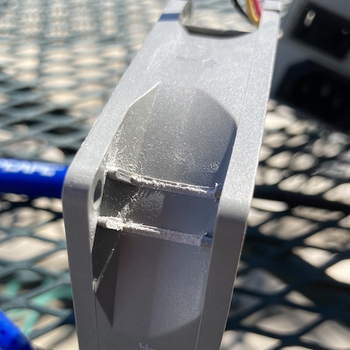
The Sanken case mounts its fan not from the front, but from the middle, on rubber isolators. Unfortunately, these classy isolators also interfered with some strenghtening ribs moulded into the Noctua, so I had to cut into my brand-new fan, in order to make it all mount.
I desoldered the old wiring loom from the “secondary” side board. This loom is on weird diamond-shaped “expanding” pins, which must be to ease assembly at the factory. Once they’re 30-plus years old, and freshly desoldered? The “expanding” part no longer works as well. I ended up having to crush them a bit with some needle-nose pliers in order to narrow the pins down enough that they would fit through the holes in the PCB.
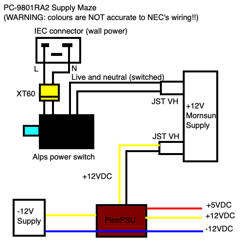
As always, it was annoying to remove the old, soldered, mains wiring from the IEC connector and the power switch. I first looked around to see if I could find a substitute that used crimp pins. Crimp pins are both much easier to work with, and also are usually required by modern electrical code, probably because they’re much harder to screw up than a soldered connection is.
Unfortunately, the vintage 80s Alps power switch does not really exist in a modern crimped format2, so I was forced to desolder the wiring and swap it over. To make sure that I could still separate the two sides of the power supply case, I ended up using an XT60 connector.
My desoldering technique was not great. Because I’m always afraid of melting the pins out of the plastic body of the switch, clearing the switch’s contacts went something like this:
- Flood the pins with cheap paste flux. Like, a lot of it.
- Snip the wires as close as possible so there’s less mass to have to heat up.
- Crank up the iron temperature. I was running nearly 425°C, which feels very high. My poor tips.
- Add fresh solder to the existing solder, producing a huge glob of nasty/nice solder. Suck as much of it as you can with the desoldering pump, without melting the pins out of the connector.
- Add more flux.
- Take a deep breath and apply heat to the pins and wire for a really long time, until the wire seems to come free, and then pull it away from the connector using pliers or tweezers. Don’t get burned. I said don’t.
- Clean up all the leftover globs of solder from the connectors using braid, and also from your desk and clothes.
I’m also not super happy with the XT60s, either. While they are presumably okay to 60A (and if the mains connection sees even half of that, something has gone really wrong with everything, including my house’s breakers) I didn’t have any heat shrink that was a perfect match to the pins’ diameters. Not wanting any exposed metal that could possibly touch the case and therefore earth, I ended up wrapping it with electrical tape as an extra layer of security.
Speaking of heat shrink, I bought some 6mm 3:1 clear adhesive-lined double-walled heat shrink from AliExpress before I started this project. Thin bands of it work much better than zipties or split loom for keeping wire bundles together.
I used my back-stock of JST VH pins, connectors, and crimpers to put together the rest of the harness. I was extra lucky that the knockoff PicoPSU I chose to use also used JST VH for its +12V input connector, so I ended up depinning that connector and pushing my crimped wires from the Mornsun right into it. Nice to not have to buy new 2-pin JST VH housings, since those are out of stock too!
The Moment of Truth
After doing a lot of cable management and squinting at connections, I was finally able to close up the finished supply. Before applying power, I did a lot of continuity tests. I wanted to make sure that power rails weren’t shorted together (i.e. that I put the wiring harness in the right way around) and that the high-voltage lines weren’t shorted to the case.
Once all of that was done, there was nothing else to do but plug it in and let her rip.
As always, the Noctua cooling fan is so quiet that it’s hard to tell that the machine is on. Good thing the Mornsun has a creepy blue LED to go with it.
I quickly tested -12V on the output harness. It was there!
After dismantling the computer’s entire case again, I was able to stick the supply in. Welcome home!
Fired Up
I plugged it into my GBS-Control upscaler and the power, and pushed the power button. Immediately came the familiar pipo of a happy PC-9801. Although the video was scrambled (wrong sync configuration on the GBS, quickly remedied) I could tell that the little machine was doing its hardest to come out of torpor once again.

After taking a long time to check all zero of the SCSI devices on the bus, the SCSI card’s ROM returned control to the system. N88-BASIC appeared, asking me how many file handles I wanted to reserve.
Great! A working computer. Or so I thought…
Repair Summary
| Fault | Remedy | Caveats |
|---|---|---|
| Battery leakage | Neutralize leakage with vinegar, clean with alcohol, inspect and reflow joints. | More unseen damage may lurk under ICs. |
| Little rubber feet fell off | Stick them back on with Gorilla Tape | |
| Broken floppy lever | Epoxied together and (poorly) painted. | |
| Broken floppy lever (after repair.) | Make whole new ones using 3D printer. | They’re not perfect replicas – yet. |
| Neither floppy drive allows insertion of diskettes | Remove broken-off “head protector” from drives. | |
| Original power supply cooling fan was clogged, grindy. | Replace with new fan. | Some trimming was required to the new fan in order to make it fit the PSU bracket. |
-
The best way to describe Artdink is “confident.” They do the quirky games that they want to do, even if those games are hot-air ballooning simulators. I love them, even if I can’t always understand them. ↩
-
In general, it seems to be hard to find new toggle switches that handle mains power at all. I assume they are falling out of favour in general for safety reasons, as it’s much safer to have a human-touchable switch handle a small standby DC power rail instead, like on an ATX power supply. ↩