Mastering the BASICs
Tags: computer hitachi basic-master pickups
Hitachi made a bunch of computers, none of which seemed to have that much penetration in the Western market. Perhaps their most popular series was the Basic Master. This very late model of BASIC Master has floated into my life.
What is the Basic Master? The easy explanation is that it’s a 6800- or 6809-based personal computer. Its first model, retroactively the Basic Master Level 1, was released in 1978 – that’s a time when there really were no options for domestic personal computers in Japan except the NEC TK-80. This machine represented an excellent deal: for ¥188,000, a little more than twice what the ¥88,500 bare-board TK-80 cost, you could get a full QWERTY keyboard, an NTSC composite or RF video output, and four kilobytes of RAM in a handsome case. It’s also notable for being the first mass-market personal computer to be able to display kanji.
Hitachi also tried to fight off the PC-6001 by repackaging an older 6800-based Basic Master model as the “Basic Master Jr” and selling it as a cheaper home computer. Of course, such a thing is foolish. No one can defeat the PC-6001.
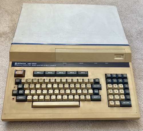
This particular Basic Master is a Level III Mark II, model MB-6891. It combines Apple II-esque good looks with a 6809 CPU and colour video. There’s also a ton of expansion slots, none of which were filled on my model.
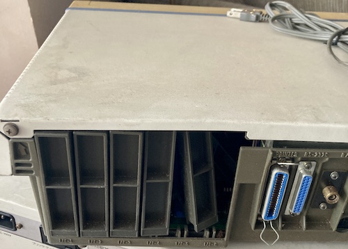
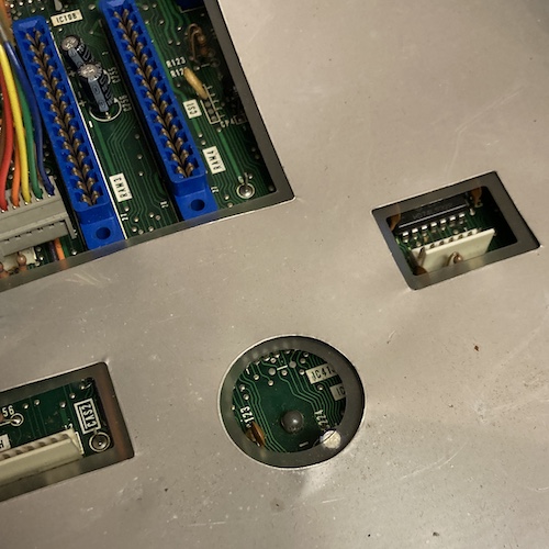
Six slots for expansion cards and two “RAM” slots are on offer, which means a large portion of the motherboard is dedicated to holding those slots. No cards were included in mine, and all the slot covers were present, which makes me think this computer was never upgraded. Boy, it’d be fun to build a card for this.
A later model, the Mark 5, introduced a programmable character generator so the font could be redefined at runtime. Eventually, the entire line was replaced by the much fancier Hitachi S1.
Foamectomy
When I got the computer out of the box and unwrapped the bubble wrap holding it together, I noticed that some of the plastic expansion slot covers had been knocked out of the back in shipping. The metal cover on the back of the machine was bent, and a couple of the plastic alignment pegs holding it straight had broken off.
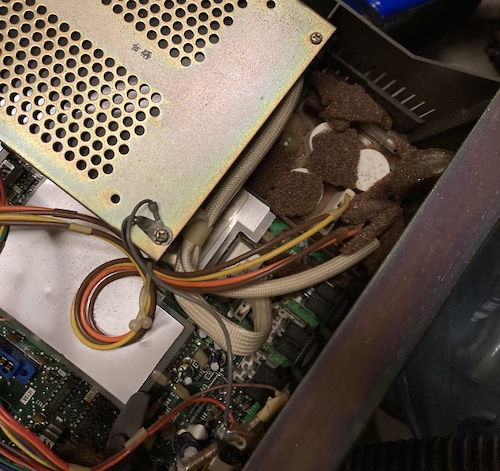
What’s more, there was also some kind of brown-red foam falling out of the computer, which made my hands itch furiously when I handled it. This got the computer condemned to the garage for a little bit, until I could give it a date with the Shop-Vac, just like I did with the X68000 PRO’s insect residents.
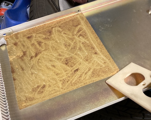
As foam disappeared into the Shop-Vac (sometimes getting wedged and exploding into tinier pieces of foam, a la Asteroids,) I turned my attention to the adhesive pad that had been holding it onto the top of the case. This had failed long ago. I had no luck scraping the adhesive pad off in one shot, so I decided to just keep it there and scrape as much of the foam residue off as I could. Here’s a pro-tip: old light switch plates work just as well as plastic razor blades for removing stickers and scraping gunk, and they’re a lot harder to lose in your shop because they’re obnoxiously big.
After about an hour of work, I finally had the machine torn down to the bottom plastic and could vacuum it out of all the nooks and crannies. All of the old plastic had swollen around the screws holding the motherboard in, making the screws perilous to remove.
What’s worse, a central holding post/clip for the motherboard wouldn’t let go of the board. Not wanting to twist the delicate board to try and fight the plastic, I decided to sneak in with side cutters and just trim the post off. This took awhile too, but ultimately I was able to get the motherboard out and slip it out of its plastic-covered RF shield.
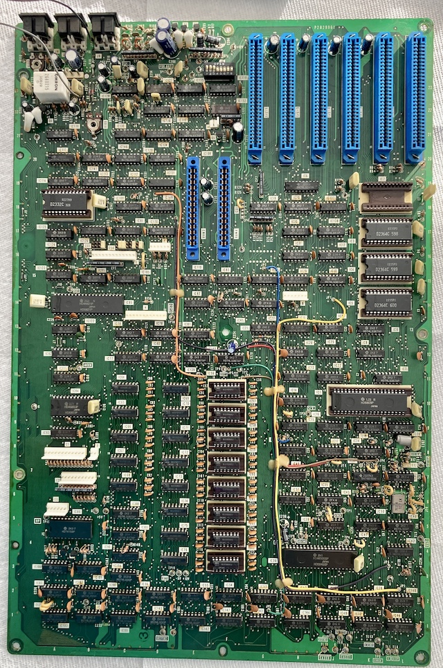
Video on this machine is 6845-based, just like the Sanyo MBC-555 I covered previously on the blog.
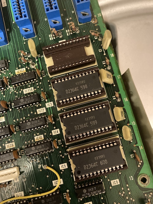
I thought it was a little weird that there were only three ROMs on this side with one ROM socket left empty, but the board also had a µPD2332 ROM that I didn’t photograph on the other end. These are neat-looking sockets that have a surprising amount of height off the bottom of the board. I am guessing the missing ROM is likely a dictionary for the kanji option, which this computer didn’t come with.
I noticed that the foam had left behind very sparkly dust, and sparkly dust made me think “conductive,” so the board got a trip to the sink to try and scrub all of it off.
After it dried, I wanted to make absolutely sure there was nothing lurking between the pins of the DIPs. On the X68000 PRO, I had also used “ColorCoral” (sic) keyboard cleaning goop to clean the motherboard. Eric from TubeTime had suggested it originally, and it worked out great at pulling biological slime and leftover debris from the PRO’s motherboard after its third or fourth wash.
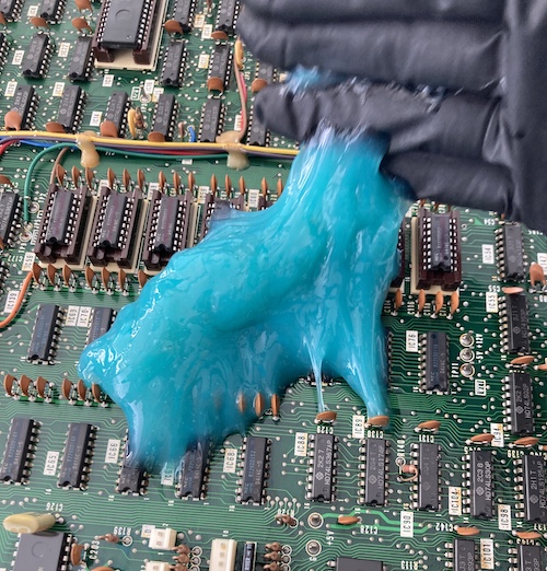
It worked pretty well here, pulling up a large quantity of dust, though it didn’t turn a gross dark colour like it did with the PRO’s much filthier board. Still, I felt a lot better having used it, and I started to reassemble the computer for its test flight.
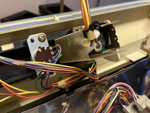
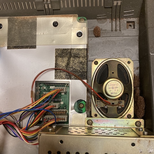
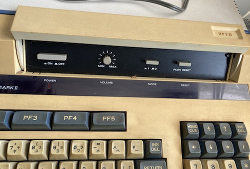
The power switch inside the “flip-up” door takes up a lot of room inside the computer, both from its giant harness and the overkill mounting bracket that’s holding it in place. Its neighbour, the volume control pot, is no slouch either.
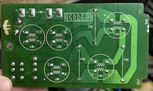
There is a little sub-board that the line voltage goes into before it is brought up into the power supply. On that board, in addition to the usual fuses and giant capacitors, are these weird white four-pin guys. I think they must be some kind of choke, but why so many?
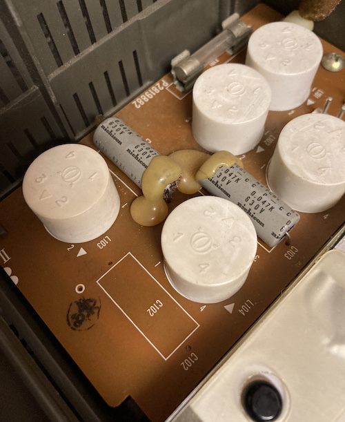
They remind me a little bit of the turrets in Zaxxon.
Reassembly wasn’t too difficult at all, although I did forget which connector went where. It’s a good thing I took photos during the disassembly, as foam-covered as they were. Maybe one day I should invest in a head-mounted camera or something, to get all the really good stuff?
Inspecting the Computer
This computer has one of the most satisfying power toggle buttons I’ve ever experienced. It’s super wide, and it’s chunky. There’s no wobble as it goes in, despite its size, giving a great first impression. That power button is also under this little hatch on the front, which has a mysterious “mode” button I didn’t initially grasp the purpose of.
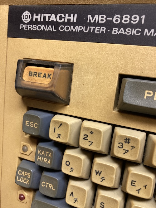
The bright yellow “break” key is in a little clear plastic shield, so you can’t accidentally hit it when reaching for a different key. Pretty clever, and I’m sure it was expensive to add.
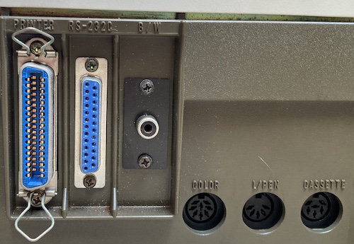
Hitachi was generous with ports on this one. There’s six expansion slots to add whatever else you want, but it’s pretty handsomely equipped out of the gate. The middle portion holds a Centronics(!) printer port, a 25-pin 4800-baud serial port, and a black-and-white composite video port.
On the right side, you see a “colour RGB” 8-pin DIN (more on that in a bit,) a “light pen” control port, and cassette. Tape is probably my best bet to get software onto this thing. I know the baud rate is 600 and the pinout is available too. It’s a little weird to see a 6-pin cassette cable.
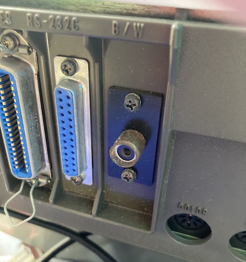
I wasn’t sure why the black-and-white composite-video RCA jack was covered in this shrink-wrap tubing. Because it has obviously shrunk over the years, it was difficult to get a composite video cord in here. Eventually I triumphed, at which point it slid right off and cracked.
The exterior of the machine was ultra-filthy, so I gave it a quick scrub with a Lysol wipe. Make that three wipes. Eventually they stopped coming away black, and I was able to move onto the keyboard, which I unsatisfyingly half-cleaned using a gentle scrub.
Maybe I should’ve saved some of that keyboard-cleaning goop for the keyboard, huh?
Firing It Up
Now that the machine was reassembled and I had given it the absolute basest cleaning, it was time to run power through it. I knew that it energized based on the Yahoo! Auctions ad showing the power light turned on, and since my cursory inspection of the power supply didn’t show any hidden nightmares, I figured that it would at least start.
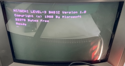
For the first run, I used the composite A/V connection (marked B&W on the back.) This fired up quickly on my long-suffering PVM, and produced decent video. I was able to enter the usual “hello world” infinite-loop BASIC program, and then move onto playing with the other features. I did notice that scrolling was incredibly slow, compared to other 8-bits of the era.
Although the keyboard felt notchy as I was reassembling the machine, all the keys seemed to respond – and respond well. In addition to the relatively pleasant mechanical feel of the key strike, the bottom-mounted speaker also plays a PC-6001-esque “clack” noise whenever a key is struck (or autorepeats.) Eventually I turned this down using the front-panel volume switch, as I found it a little harsh.
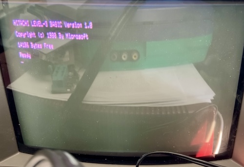
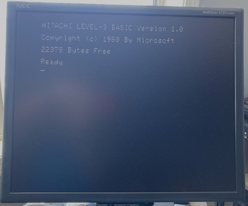
I wanted to know what the mysterious “MODE” toggle switch on the front was for, so I pushed it. Nothing seemed to happen. I pushed reset, which produced an “aborted in line xx” alert and didn’t soft-reset the computer. So I switched it off and back on again, and now I was in what appeared to be an 80-column high-resolution video mode!
Considering this is going into a 9” 200-line TV that is approximately twenty years past its use-by date, this is pretty sharp video. Monochrome is the way to go for terminals, I am convinced.
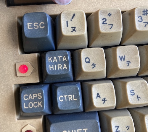
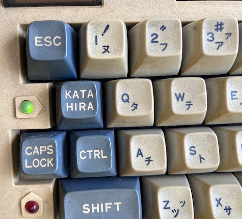
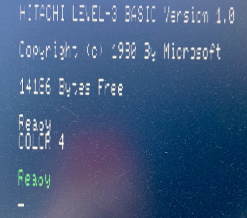
This is a super cool little thing. The same “bulb” on the top can be shown in two colours depending on what character input mode you’re in. In katakana mode, it’s red. In hiragana mode, it’s green. This computer is full of fun little premium touches like this.
In general, my first experience with the Basic Master was pretty pleasant. There was a bit of a stink that developed as the machine heated up, though. Also, I wanted colour. Let’s get some RGB in here!
Master the Colours
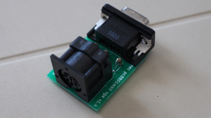
I had a strong suspicion that the 8-pin DIN “colour video” connection was in fact the same digital RGB connection I’d seen on many other Japanese machines. The 150Ω “stepdown” RGB adapter that I’d made so very long ago for the NEC PC-8801mkII had shown itself to work for the following computers:
- NEC PC-8801mkII, mkIISR;
- NEC PC-6001mkII, PC-6601SR;
- Many NEC PC-9801s;
- Fujitsu FM-7, FM-8;
- Sanyo MBC-555
Before connecting it to a monitor, I plugged the adapter into the computer and turned it on. Using a voltmeter, I made sure that none of the pins were showing a potentially dangerous voltage like +12V. Although I’m sure NEC has put in a lot of protections, I don’t want to have to go buy a new monitor for a dumb reason!
Everything looked okay, so I powered off the computer and plugged in the whole assembly.
The same RGB adapter worked for the Basic Master too! The monitor detected it as 15kHz.
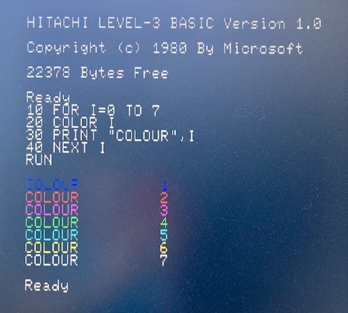
Let’s make sure I got the colours right, and Hitachi isn’t trying to pull a fast one on us by moving the RGB pins around. I used the MAME bml3 driver1 to check what it should look like.
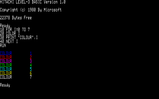
Great! Based on this string of successes, it makes me suspect that Japanese digital-RGB monitors were trying to follow a sort of standard pinout, possibly set by this series of machines. I’ll still check every weird new machine in the future, but I definitely feel more confident now.
I wanted to check if colour would also work in 80-column mode, and it did! I didn’t want to adjust my monitor and screw up the settings for later, though, so you’re just going to get this ugly picture of it.
Conclusion
It’s always fun to pick up a new machine, especially one you don’t have any experience working with. I got incredibly lucky that the RGB pinout was shared with other machines and that the computer worked as well as it did. Although I’m still researching what to do next, you haven’t seen the last of this computer. I’ll be hunting for documentation2, so I can figure out how to use it, and trying to figure out how to load software from tape or a serial port. Maybe I’ll finally get to try my hand at 6809 assembly?
On top of that, I really want to do something with all these expansion card slots to justify such a bulky machine. Thanks for following along with this adventure, and if you have any helpful information about the system or a source on the software, please let me know!
-
According to my copy of MAME 0.243, a lot of the ROMs need to be re-dumped. I’m not sure exactly why, but I will see what I can do about dumping these 2364s in the future. ↩
-
I/O magazine published a supplemental bookazine about the Basic Master hardware and system calls, ベーシックマスター活用研究, or Basic Master Utilization Research, which I’d love to track down. It contains a lot of contest-winning programs as well. It’s in the national library – this poster used it to make an emulator – but that is not really convenient for me. ↩