A Backup Papicom
Tags: computer nec pc60 pc6001 pickups corrosion repair power-supply
When you love a computer, sometimes you have to buy a second one of that computer, especially if it’s cheap. My justification? I wanted a good sacrificial test platform on which to do a bunch of internal PC-6001 mods, and I didn’t want to worry about frying my beloved first PC-6001. So, of course what I did was: pick up one that’s in better condition than my “good” one.
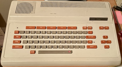
This system is a lot crisper than my original machine. Not only is the plastic largely scar-free, but the keyboard doesn’t bind up on either edge, and I didn’t have to clean any rust off the composite video port. There’s just one major cosmetic flaw.
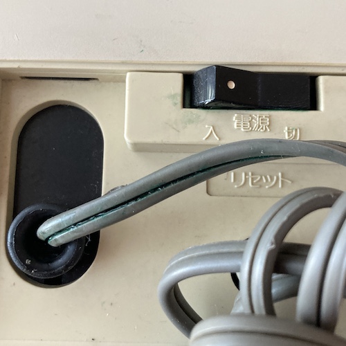
Right off the bat, I noticed that the power switch was unpleasant to use. This is a surprise, because the 6001 has an excellent power switch. The reason? The plasticizer in the power cord is breaking down, releasing blue-green copper corrosion and making the insulation super brittle.
It looks like the switch has gotten clogged with this noxious, sticky garbage, and will need to be deep-cleaned. I definitely don’t want to pass high voltage through it.
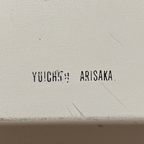
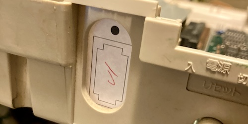
There’s also a dye-stamped marking on the top of this case, which may be the previous owner’s name. “YUICH… ARISAKA” is all I can read, as some damage to the case has obliterated the stamping. If you think you know who this person is, please let me know, because it would be fun to speak to them and learn what they used this for.
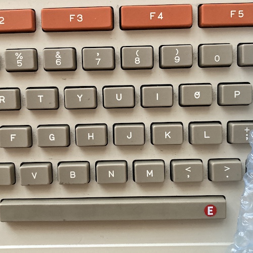
There’s also an interesting “E” sticker here on the space bar. Please note that the “O” on the PC-6001 keyboard, like on Fujitsu machines, is written funkily, maybe so that the number zero and the letter O are not confused by Japanese children and adults not used to Roman characters.
In terms of equipment, this PC-6001 is basically the same as my other one. There’s no keyboard overlay insert, there’s no serial card, and there’s no internal bodge-wired upgrades. However, there is evidence that someone has been inside monkeying with it, because four out of the six case screws were missing.
Pulling It Apart
As always, getting inside a PC-6001 means dealing with the giant heat/RF shield. There’s a big switching transistor that is glued on top with thermal paste, which gets everywhere. That goopy power cord added additional complications, too, as I tried my best not to spread the super-sticky green death all over the place, or get it on my hands and screwdriver.
The big heavy transformer was lifted out and placed on the floor. It sure left a lot of tempting room behind.
Because the power cord was so brittle, I decided to remove it from the system altogether, which made it much easier to pull the power supply board out. It was at this point that I began to get some very bad ideas about how to make this particular PC-6001 more efficient, lighter, and easier to maintain in the future.
Why did I bother taking this thing all the way apart, if all I really needed to replace was the power cord and switch?
Dumping It
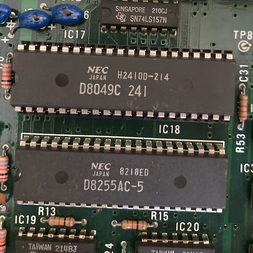
Outside of the ROMs, there is only one custom part on a PC-6001 – the keyboard controller, which is a standard mask-ROM NEC 8049 microcontroller. Everything else inside one of these little miracles is off the shelf. If I were to, say, clone the PC-6001, it would be handy to know what’s inside that keyboard controller.
I used my HvEPROM MCS48 dumper to dump the µPD8049HC microcontroller on the motherboard. This 8049 seems to control both keyboard and cassette audio, as per the I/O schematic.
Dumping this actually helps out at least two people:
- The dump is not in MAME, which means the emulated PC-6001’s cassette tape and keyboard handling is a little weird;
- It had failed on an NEC TREK (the American release of the PC-6001) owned by a friend of someone in the PC-98 Discord, so I offered to dump one of these to see if the machine can be resuscitated – and now I am finally getting around to that promise.
The dump was pretty easy: I removed it from the (exceptionally tight) socket, and stuck it in the programmer. You can find the NEC PC-6001’s µPD8049HC-241 dump here on the Internet Archive.
Unfortunately, I found out only after I had submitted it to everyone that it was a bad dump. Subsequent redumps produced different dumps, which meant the 8049 was not being dumped properly. I had to go back, hat in hand, and explain that I had screwed up and had no idea what I was doing.
After some more review, I found out that my build of the HvEPROM MCS48 dumper was not properly controlling the 12V line on the MCS48’s “PROG” pin – its rise time is eons long. I am not sure if I swapped two resistors by mistake or if I just got some bum parts. More on this later.
Power Cord
The original power cord was junk. Super hard, bleeding green stuff, and generally irritating: no need for that anymore. I chopped the power switch out of the cord, and then worked hard for about ten minutes to free the strain relief from the metal bracket (you have to pry the metal outwards while wiggling the strain relief out.) After that, it was a simple matter of lifting the little clip on the strain relief to free the cord, and then a strong yank pulled it (and about ten pounds of sticky green crap) out.
I decided that I would also replace the wires going into the power supply “AZ” connector. They were also greened-up, and it didn’t make sense to go through all this effort just to have a bunch of other gunky forty-year-old wires to deal with. I depinned this connector by using a set of depinning tools I had lying around. NEC uses this connector a lot, even in 90s stuff like my MultiSync 3D, but I found it difficult to find a source on replacement ones.
After awhile of thinking about this, I realized that I simply don’t like having cords dangling out of my old PCs. Although it’s easier to set up, it makes it harder to stack and store. Not only that, but the 80s ones have a tendency to leach out all their plasticizer and corrode things around them, including “cord burning” the plastic. All this is common with little Japanese 8-bits, and is probably my bête noire of owning them. Other than batteries, that is. I hate batteries.
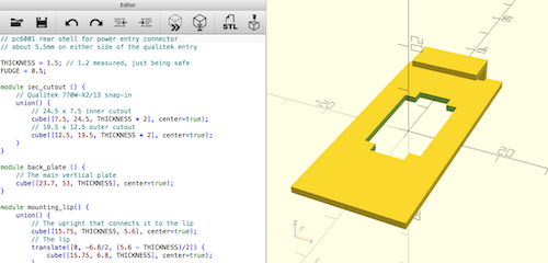
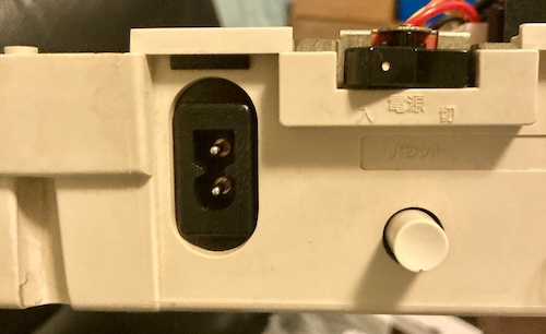
I wanted to try and use a polarized IEC C7/C8 connector. This “kettle lead” is very common on a lot of electronics, so I thought it would be easy to find on Digi-Key. It was: the Qualtek 770W-X2/13 both rolls off the tongue and is a widely available part. If there is a downside, it’s that it was kind of expensive at about $1.95 a pop1. Oh well, it’s not like I’m going to be converting a lot of PC-6001s, it’s not like anyone is stupid enough to own a lot of them. Wait, I own a lot of them? How did that happen?
This took a lot of fiddling until I was happy with it. Luckily, paper prototypes are a lot cheaper and faster than JLCPCB 3D prints.
Normally, I would have done a PCB for this task, but the original PC-6001 power cord retainer has a little lip on the top that levers into the plastic. Because of this, I decided it would be a good fit to make into a 3D print instead. OpenSCAD came to the rescue, and I was able to bang out a cheap little bracket almost as fast as I could take measurements. Thanks, OpenSCAD!
I used JLCPCB’s “X Resin” service to order this. “X Resin” isn’t a particular resin, it’s basically their way of saying “we’ll run this with whatever was loaded into the printer last, we won’t sand it, and in return it’ll be dirt cheap.” I like that last part. Unfortunately, because it’s sort of a wink-wink-nudge-nudge deal, they don’t let you order more than two of them at a time. So we’re only going to do some of the PC-6001s with this “kit,” I guess.
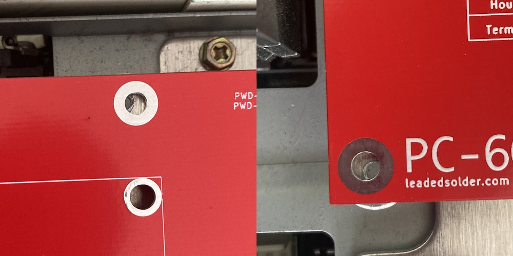
When it arrived, I was very pleased with the quality and the strength of the part. I was able to slot it right into the case, and it fit well.
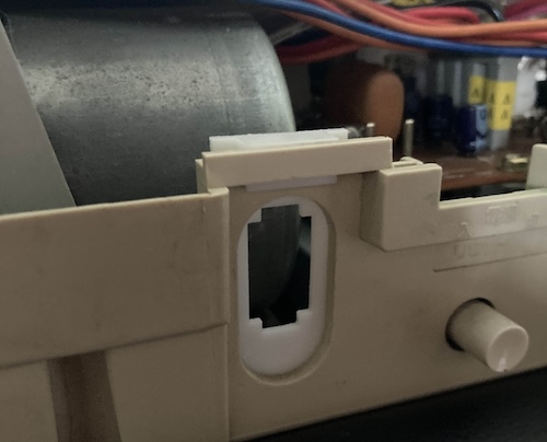
Sure, I put the hole up instead of down from the top like I should have, but that’s why they put erasers on astronauts.
As expected, though, the IEC connector clips right in. Fantastic!
Power Adapting
I thought about it some more once this adapter plate was designed, and I realized I also didn’t like having a super-heavy transformer in the case, either. That’s not at all because I forgot to measure how deep the IEC connector goes into the case, nor is it because that connector then fouls on the enormous transformer sitting right behind it. Those are just coincidences.
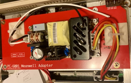
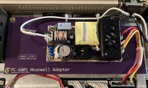
To revive a PC-9801UV in the past, I’ve used a Meanwell RPT-60B. This insanely tiny little open-frame power supply accepts wall AC, and outputs +5V, +12V, and -12V: everything the PC-6001 needs to be a happy little camper. It also runs very cool, has extra safety features, and provides a higher wattage than the original power supply. It is also intended for use in a 120V country like Canada, which should help me sleep a little better at night.
There was one more mystery to be solved. What about -5V?
Back in the original PC-6001 article, I mentioned that I probed the -5V pin on the cartridge slot. Negative-five volts are also required for the proper function of the µPD416C DRAMs on the motherboard, but there is no pin for this voltage on the motherboard’s power-supply connector!
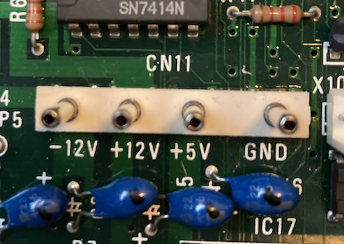
So, where’s that voltage coming from, if not right off the PSU into the motherboard? I checked the schematic…
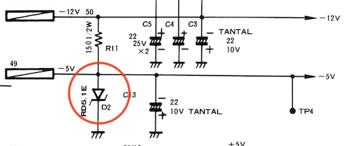
The oldest trick in the linear-regulation book: a Zener diode voltage regulator. NEC derives the -5V rail from the -12V rail, right on the motherboard. In other words, I don’t have to worry about that when I do a Meanwell swap. RPT-60B ahoy!
It is a little annoying that I have to make a board this big just for the sake of the mounting holes. I’m sure there’s something else that it could be doing, but for now, that big empty space is just delicious ground pour and helpful text instructions.
Any More Supplies?
One other benefit of making a new two-sided PCB for the power supply mount is that virtually all of it is ground pour. The Meanwell sits on top of it and does its thing, and now we have a big chunk of copper to clamp things to. My hope was that I’d be able to run some fly wires to it in order to improve the Japanese-market PC-6001’s poor video quality.
I kept racking my brain to try and figure out something functional to do with this PCB. It felt bad to make such a big one just to hold up another module that does all the work, so I added some informational text. Maybe I’ll come up with something to do with all this empty board room in a future version.
Maybe you have a cool idea! Let me know. Fan power would be a good option, especially run off of a temperature sensor, except that now the system runs significantly cooler, and there’s not enough room left on the board to mount even a dinky little 40mm.
Kill Switch Disengaged
There is one big problem with the use of these Meanwells that I didn’t fix, though. Because they don’t have remote on/off power pins, they can’t be turned off by logic, only by cutting the source power to them.
This means that the pair of parallel power-kill switches in the original PC-6001’s cartridge slot, which are designed to keep you from damaging something if you pull out or insert a cartridge while the computer is running, will unfortunately not function.
Meanwell doesn’t make a power supply with remote on/off switches in this form factor, as far as I can tell, and I didn’t feel comfortable figuring out how to safely use a solid-state relay to switch low-voltage/high-current power right on this board. If you have a cool idea for how to do this, please let me know! I would love to add this to a later version.
A PicoPSU does have soft-power (since it’s an ATX supply,) which made me consider designing something similar to the X68000 PRO power supply PCB. Unfortunately, the -12V current limit on the PicoPSU is very low at only 0.05A, and I’m not exactly sure how much the PC-6001 demands on this rail, or even how to estimate it. Another good thing to measure, and possibly to change direction on a later version.
For now, the current design means that you will run the risk of damaging the system or the cartridges if you hot-swap cartridges. I think this is an okay compromise to make, for my personal use. We’ll see if I regret this choice later!
Having soft power would actually be super cool, because then I wouldn’t need to use a vintage power switch. And that’s important, because…
Power Switch Cleaning
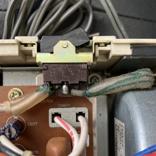
Unfortunately, the power switch (what appears to be an ALPS SDA3L, 41-10792) also got filled with green death goop from the power cord that was soldered to it. I searched for a replacement for a while, and decided finally to clean and maintain it.
My first stop was to desolder everything from the pins using lots of flux, and then stick it in a ziploc bag with distilled water and some dish soap inside my ultrasonic. The bag means that I don’t have to use as much solvent, so the outside water bath can stay fresh for longer, which is good because it’s a pain in the butt to drain and refill the entire ultrasonic tank.
Once it had been run through the ultrasonic for about 20 minutes, a lot of green crap had been pushed out of the inside of the switch and out through gaps in the casing around the pins. I cleaned this gunk off with a significant number of q-tips and shop towels, and dismantled the switch by pulling its crimps apart with pliers.
Inside the switch, all the metal parts looked generally okay. One of the leafs was more oxidized than the other one, probably from poor contact, so it’s a good thing that I was in here. I let it sit in a plastic container of isopropyl alcohol for a day, and I was a little shocked to find out how much gunk had come off just from a simple alcohol bath.
As with the power switch in the Tomy Pyuuta, this Alps-style power switch works by see-sawing a pair of arched metal contacts (one live, one neutral) using a rubber finger on the inside of the rocker itself.
All of the plastic parts inside the switch have been bleached by the noxious goo coming off the power cord. I attempted to add some grease to the pivots, and tried to keep it off of the contacts. Eventually, I just soaked the entire thing in Deoxit and hoped for the best. I brushed the contact pads of the switch leafs clean with a Gerryflex block, but you could probably even use a Magic Eraser.
After checking to make sure there was continuity when the switch was turned “on,” I proceeded to re-crimp the switch and feel very satisfied. For a moment or two, that is. Then it was time to keep moving.
Version 1
Those of you who are participating in the Leaded Solder drinking game can take a shot for “obvious PCB measurement error.” Sorry about your liver.
Yep, I made a big ol’ error on the PSU board when I measured it. All my measurements were just a little bit off when I transferred the holes to paper and then KiCad:
Okay, some of these are quite a bit off, more than could be explained by PCB warpage. I think I measured from the edge of the holes instead of the centre of them, forgot this detail, and then used that measurement to position the centre of the holes when I got up to KiCad. I also found out that I had misremembered the diameter of the holes, which is basically the kiss of death either way.
I should have taken more time and measured from the holes on the backing plate, instead of trying to measure the PCB. It might also have helped to print this out and try to install it before rushing to order, but I didn’t want to cut out the little holes from the paper copy.
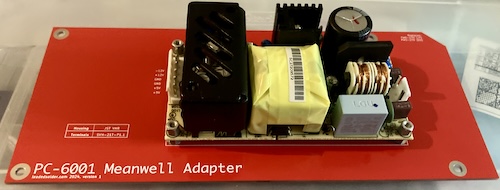
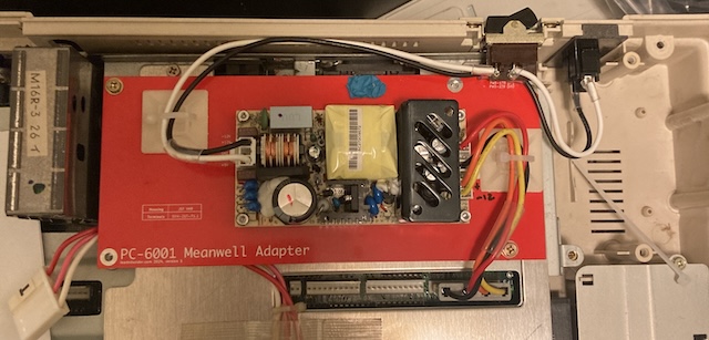
Even so, through the magic of trigonometry and holding my tongue in just the right spot, I was able to get two corner holes screwed down. And I found an RPT-60B in my parts pile! And it fit perfectly!
Another bug, but a minor one: in the position where I initially decided to put it, the power-supply harness to the motherboard is not long enough. On the original PC-6001, it comes out of the right side of the board, but I put it on the left, so it has to cover like three more inches of wire length that it doesn’t have. That’s easy enough to fix, though: I can just ignore the silkscreen and spin the Meanwell around.
I found these stick-on ziptie “pyramids” in my parts bin. You can stick them onto a board, and then slide a ziptie through them in order to hold down the cables. To give them something to hold onto, I crimped up my mains and output cables.
Unfortunately, I don’t know what the connectors in use are for the motherboard side, so I wasn’t able to crimp up and run new wires. These 40-year-old ones will have to do a couple more years of service instead.
Now came the time for some bravery: soldering onto the power switch that I had just spent so much effort and time saving. I am always nervous about this kind of thing because I don’t want to overheat and melt the contacts through the plastic of the switch. With some careful planning (and probably tactical cowardice) I was able to get away with the switch and IEC connectors mostly intact.
One thing that’s very annoying is that the switch is way too close to the power supply PCB for my comfort. It’s not touching, obviously, but it’s close enough that I went back and cut that whole corner out of the PSU PCB for a hypothetical future “version two.”
In the meantime, though, that IEC connector looks really good:
Whew! That was a lot of work.
Version 1 Testing
Before firing it up, I decided it might be a good idea to re-check those pesky tantalum capacitors. This board still has its original troublesome caps. They weren’t shorted, so I went ahead and reassembled the PC-6001.
Time for a first test fire: and nothing. No video, no sound, no power lights. On the Kill-A-Watt, I could see that the machine was pulling about 0.11A, which should be pretty close to how much the Meanwell demands in steady state. I quickly shut off the system and inspected it.
Sure enough, the +12V tantalum cap had immediately shorted on the inrush from being awoken for the first time in years. Unlike the stock power supply, the Meanwell is smart enough to shut itself off when it detects a short on any of the rails: the original will bring up the other voltages like nothing happened, which can reportedly kill the triple-voltage DRAM in these machines. See? It’s safer already.
I don’t know why I thought I could get away with not replacing the tantalum caps on the motherboard: they have blown in literally all of my original-recipe PC-6001s. I have replaced so many of these little bastards.
After throwing in some replacement caps for four of the troublesome tants, I was ready to flip the switch again. This time, everything started up just fine:
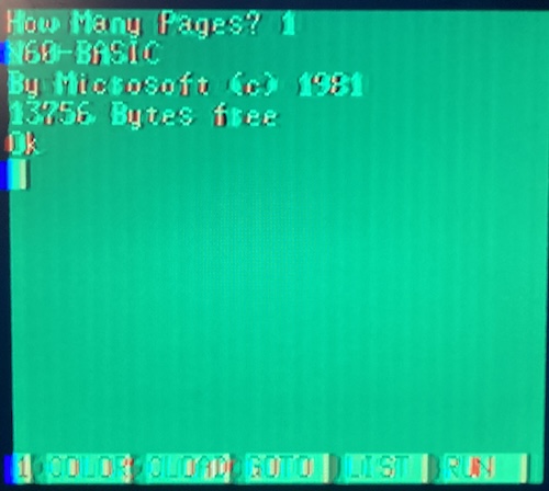
Why does the video look so bad? There’s a couple reasons:
- The Meanwell is a switch-mode power supply, whereas I am about 70% sure that the original supply was linear. This means that you end up with more noise from the back-EMF from switching the transistors on and off. Its original capacitor setup was built to be A: cheap and B: filtering out linear noise. This can probably be mitigated with better grounding and throwing a couple more decoupling caps on the board.
- The Samsung 910MP LCD I’m using this on has disgustingly poor composite video quality on literally any source. The previous owner told me it was struck by lightning. There’s only one cap on its input and I’ve already replaced it, so it may also need additional filtering caps. It looks better but not great on a cheap department-store CRT.
- The Japanese-market PC-6001 is much less aggressively shielded than the American model. The American model adds additional shielding to basically every component of the system, especially the RF modulator (that is also responsible for composite video amplification.) In a future article, I will be retrofitting some of those mods to this system to see how they affect the video output.
- 6847 composite video output looks bad on everything. It’s based on artifact colour, like the Apple II, and seems to screw up LCD scalers such as the one inside the 910MP. In other words, the PC-6001 has never had great video quality.
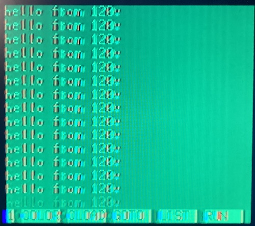
All this doesn’t stop me from banging out a quick little print program, and I was delighted to find that this is by far the best keyboard of the three original-recipe PC-6001s I own.
Conclusion
Sometimes a project doesn’t end up where you think it will. I certainly did not expect to build a whole new power supply board for “this power cord is gross.”
I have already obsoleted this board with version two, which puts the mounting holes in the correct place, fixes the labels for the inputs and outputs to the “rotated” Meanwell, and adds some snazzy zip-ties to keep the cabling neat.
It seems likely that I’ll probably end up with more PC-6001 PSU PCBs than I have PC-6001s. I’ll just have to buy more…
Even so, I’m glad to have gone through this project. After some more research into how to alleviate the video noise, I plan to slam this kit into all of my original-recipe PC-6001s. They all need it, especially my US-market PC-6001A. That unfortunate machine has seen so many hours of runtime that the power supply PCB and case plastic have become warped from heat.
Thanks for keeping this little computer in such good shape, Arisaka-san. If you ever visit Canada, you’re welcome to play with it any time.
If you are interested in putting a Meanwell into your own PC-6001, come check out the Meanwell adapter’s GitHub repository here. The Gerbers can be downloaded from the Releases section. Please let me know if you build one!
Repair Summary
| Fault | Remedy | Caveats |
|---|---|---|
| 8049 could not be dumped | Figure it out some other time | |
| Switch badly corroded | Un-crimp and rebuild switch with new grease | Grease may have been insufficient, not sure what kind to use. |
| Power cord badly corroded and leaking corrosive plasticizer | Remove and replace with detachable connector | |
| Power supply works perfectly well but you’re in there anyway | Build a whole new power supply PCB | Actually, make that two. Also the video quality has suffered. |
| Computer does not start after power supply replacement | Replace shorted tantalum capacitor on +12V. |
-
If you’re going to pick a connector to cheap out on, I strongly recommend that it is not the one carrying high voltage mains power. ↩