SG-1000 Ways To Leave Your Original
Tags: console sega sg1000 homemade-hardware soggy1000 clone
The SG-1000, being Sega’s first home console, has appreciated quite a bit over the years. Its price is now faintly ridiculous, especially when you consider its successor, the relatively inexpensive Mark III. Luckily for us, this console is made out of off-the-shelf components, virtually all of which are also found in the ColecoVision. If only we knew someone who’d cloned the ColecoVision…
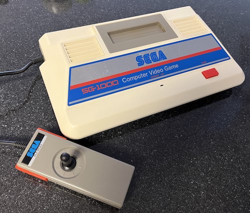
Just how similar are the SG-1000 and the ColecoVision? Well, they use the same Z80 CPU, TMS9918 VDP, SN76489 sound chip, and basic design. The ColecoVision is much more complex, with a BIOS ROM, four pages of cartridge ROM banking, quadrature controller support, and a very sophisticated expansion bus.
They also share a lot of the same downsides: fragile and uncomfortable controllers, RF-out only, an expensive boondoggle of a home computer platform based on it, and being mercilessly crushed in the market. I assume that it’s easier to find a ColecoVision in North America than it is to find an SG-1000 in Japan, but I don’t really know the production numbers of the latter.
The two systems are so similar that you were once able to buy both of them in the same case. Bit Corporation’s Dina, also known as the Telegames Personal Arcade in North America, mashed both machines together on the same board and offered two cartridge slots1, one for each machine.
The Mission
This project has been bouncing around in the back of my head ever since I started Leako, my clone of the ColecoVision. The SG-1000 is a much simpler machine, with many fewer parts, and it has just as many great games. On top of that, due to differences in palettes between the SG-1000 and the Mark III, there is no really great way to play SG-1000 cartridges in the West. You’re stuck with importing an SG-1000, SG-1000 II, or SC-3000, and my SC-3000 is still a little under the weather. The Mega SG would work, but I don’t have the cartridge adapter for it.
For the last several months, I had been telling everyone around me that maybe I’d do an SG-1000 clone in 2023, 2024, something like that – just too busy to do a huge project like this. Cloning the machine had stayed as a “one day” project.
The Construction
Then, one day, I was feeling kind of down, and the endless winter (and a recent string of repair setbacks) were getting to me. I decided the best way to feel just a little bit better was to put in a few minutes on the SG-1000 clone project. I got surprisingly far that first day, thanks in no small part to already having part numbers, known-working footprints, and a working TMS9918 VDP setup from the Leako.
My goal was to clone the original SG-1000, without a keyboard/expansion connector. I wanted to do it as quickly as possible to keep up momentum, and in through-hole rather than surface-mount. Don’t get me wrong, the surface-mount of the Leako works amazingly well, but I was feeling lazy and wanted the challenge of holding chips against the board upside-down rather than getting them perfectly straight for a nice drag solder.
I didn’t want to go nuts with improving the board too much before I got a working machine, so I ended up settling for only the following improvements on the first version:
- Composite video and mono-out audio jacks;
- USB power;
- Two controller ports instead of a hard-wired joystick for player-1
On the wishlist for future versions are obviously the following features:
- All the extra stuff to turn it into an SC-3000: SC-3000 keyboard membrane support, i8255, memory controller IC, etc;
- Barring that, providing the keyboard/expansion edge connector for the SK-1100 keyboard;
- Using more of the 62256 work RAM, possibly by emulating the Taiwanese RAM expansion cartridges;
- A built-in game/27c256 ROM socket with a switch to turn it on, so you don’t need cartridges to test it;
- A case
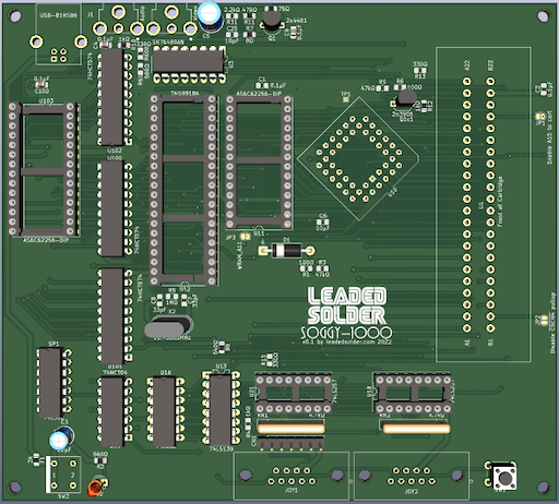
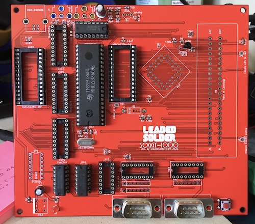
I used Enri’s SG-1000 schematics page for 99% of the layout of the machine. If you scroll down that page, you’ll be struck, as I was, with the simplicity of this machine. I am hugely grateful to Enri for all of the hard work done to make those schematics and present them in a clean way.
Confessions
Even with all the extra space, I don’t think I got a clean layout on this board. The original SG-1000 board is single-sided, and uses many fewer jumpers than I do vias, but they probably also spent more than a couple of evenings putting it together. The board is also pretty big – bigger than the Leako by about 30mm in depth – but the additional seventy cents per board in cost is not really that big of a deal, compared to saving me the multi-day routing nightmare of the Leako. I also cut corners a bit on decoupling caps. As I said earlier, this project was very much for my own entertainment, so I ended up taking shortcuts here and there in order to get it out the door a little faster.
Of course, since I went to DIP, there were a lot of 74-series parts that I just didn’t have on hand. The ‘574 in particular was difficult to find, and I had to resort to slow-boat AliExpress shipping.
Sixth time’s the charm
For this build, I had just recently switched from an ancient version of KiCad 5 to the new and exciting KiCad 6, which massively improves the push router. It is much less tiring to work with when it’s not constantly jerking your traces around all over the board because you moved your mouse 1/4th of a pixel to the left. It has a lot of other little improvements as well – my favourite new feature is the per-netclass trace width.
Its footprint editor is way, way better. For instance, it now auto-increments pin numbers when you add a pin, like in EasyEDA. It’s still not smart, but it’s a lot better. And it has sane defaults for creating edge connector pads, rather than having to mutate a regular SMD pad and, say, forget to remove the solder mask covering that pad. Not like I’ve ever done that before.
Unfortunately, KiCad 6 does feel much slower at pretty much everything – starting the application, opening a project, loading the footprint list, recalculating copper pours, constraints testing, and even writing out a Gerber take noticeably longer than before. Such is the nature of a new release, and I’m sure they’ll iron it out in future versions.
The First Big Mistake
Something had been bugging me about the joypad ports ever since I submitted the Gerber files for manufacture, and I didn’t figure out what it was until I was assembling the Leako v0.7 board.
They were the wrong way around.
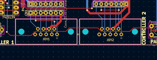
Compare to the ports on a Leako, which I am fairly sure are the correct way around because I can plug a controller in:
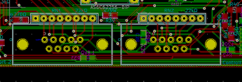
I decided that this didn’t merit another re-spin since it could be bodged, and there is still lots to test even without controllers. That said, I’m a little embarrassed that I didn’t catch such an obvious mistake when I was test-fitting the parts on the printed-out copy of the board. My only defense is that I was mostly focused on clearance for the cartridge slot and cartridge.
To warn myself in the future, I updated the footprint to have a big “BACK” indicator, and hopefully this won’t happen again. Possibly because I’m running out of DE9-based systems to clone.
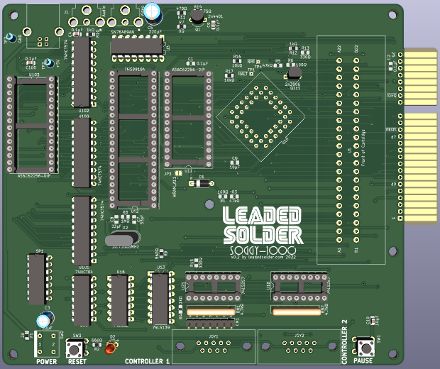
v0.1 Assembly

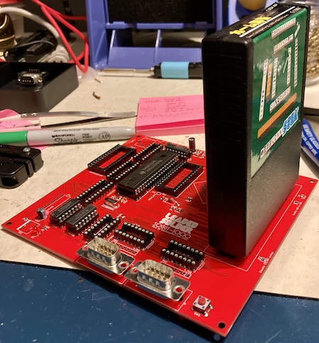
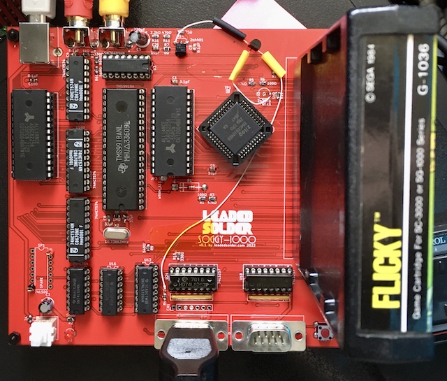
I had a surprising amount of the components on hand already from the Leako project. For instance, here’s how far I got with the assembly by just digging through my bins:
The smallness of the board really does not help the much-derided “tombstone” appearance of the game cartridges.
Due to shortages of the weirder DIP 74-series logic ICs like the ‘574 and ‘257, most of the rest of the parts were ordered from AliExpress. I used sockets so that I could pull and move the chips to a future spin of the board, but in retrospect the machine-pin sockets cost more than the salvaged ICs. The Philips-branded 574s had definitely been remarked, as the logo was smudged on about half of the chips I got.
It wouldn’t be a new console project without shipping delays, but eventually FedEx got the rest of the parts I had ordered to me, and I stuffed them into the machine.
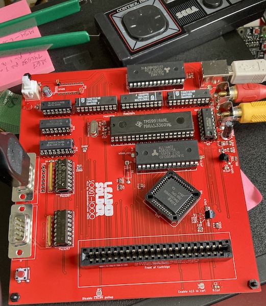
Time for the first test!
Test Fire One
It… doesn’t work. I get a blinking scanline, no sync latch on the TV, and a loud hum that doesn’t change whether or not a cartridge is inserted. Obviously, something has gone wrong.
In fact, quite a few things went wrong.
The first one I found was that the (enable external memory 2) pin, which is decoded to the second ROM/RAM bank of the cartridge, was not actually hooked up. $0000 to $7fff is meant to decode to this enable, so that would certainly explain why the cartridge wasn’t booting, as $0000 is where a Z80 should start execution.
For whatever reason, KiCad 6 didn’t give ERC errors when a local label was not connected to two things; you have to use a global label for this feature. I used global labels on the Leako project, but only because I was dealing with more than one schematic sheet. This feels like a big oversight, so I assume I’ve just not enabled the checking of local labels somewhere. In this case, I had defined an pin in the enable section but didn’t attach it to pin B19 of the cartridge. I ran a quick bodge wire for this, but the behaviour of the machine did not change, which surprised me.
From a quick assault by the logic probe, it appeared that the pin on the cartridge was now stuck low for basically forever after an initial high. That’s weird, too, as I would have expected the CPU to have chip-selected the VDP or the sound chip once in awhile if it were actually running the ROM properly.
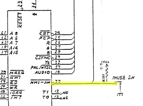
Reset and clock were moving as expected, but the data and address bus didn’t seem to be changing. The CPU wasn’t doing anything! That wasn’t the fault of the pause button, because was high unless that button was cycled, thanks to a pull-up resistor. Wait a minute.
Looking over the Leako schematic to use as a reference, I noticed that I had not pulled up and on the new board. These pins basically force the CPU into an interrupt routine or into torpor, respectively. In the SG-1000, they are are driven by the VDP and the sound chip. I had a couple of 47kΩ through-hole resistors on hand, so I pulled up those lines, but to no avail.
Testing my fix, I noticed that looked weird on the logic probe. It didn’t sound periodic, like I would have expected from a v-blank interrupt, although the logic probe’s buffering can sometimes mask higher-frequency signals like that. However, was working as expected, albeit always high, likely because the CPU was stalled and not telling the 76489 to do anything that might require a toggle of the line.
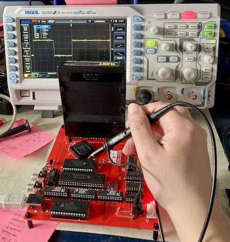
I pulled out the scope, and took a look at . It was in fact 60hz, which you would expect for a v-blank interrupt. This is a good example of how a logic probe can make you imagine things with your flimsy human senses. While I had the scope out, I also went exploring around the board. All the data and address bus transitions looked sane, and the CPU clock was running at about 3.57MHz, so the divider logic inside the TMS9918 was working.
Moving on, I found composite video at the base of the 2n4401 transistor, but not at the video-out port. Tracing backwards, I found that there was nothing at the supposed emitter of the 2n4401. Immediately, I suspected another pinout mixup, like the one I had on the Leako. I had used an OnSemi 2n4401 for that machine, but a Micro Commercial 2n4401 for this one, because the OnSemi part was being discontinued. Comparing the datasheets, it seemed like they were the same pinout.
Confused, I went through the schematic and then realized that I was voltage-dividing the composite output twice. I had copied the video output train from the Enri schematics, and then also copied the composite video amplifier circuit from the Leako schematics. They were on different parts of the schematic sheet, so I never realized the overlap.
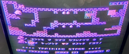
Another bodge – I cut the traces in the middle and ran a bodge wire directly from the TMS9918’s composite output pin into my amplifier circuit. This is the same circuit that was used on the Leako, so I was reasonably sure that it would work. I plugged it into the TV, and… Flicky popped up! And it actually completed the demo loop.
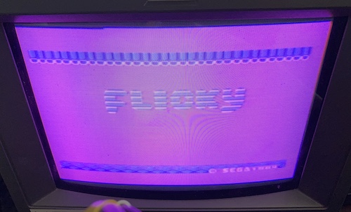
Holy crap, it works!
However, there were still some interesting problems:
- The audio output was often a loud hum instead of making any useful noise, like the SN76489 wasn’t being written to properly;
- The player-one joystick input was backwards - left made Flicky go right, and right made her go left.
- The pause button worked, but seemed to need debounce, because it wouldn’t pause or unpause reliably. Often it would just advance one frame and then pause again.
Still, pretty good.
I chopped and swapped the controller port pins first, which was an easy bodge. Then, it was off to do the hard stuff.
Soundaround
I figured I would take care of the sound next, because the constant loud hum was very annoying. My original guess was that the CPU was simply failing to write to the 76489 sound chip.
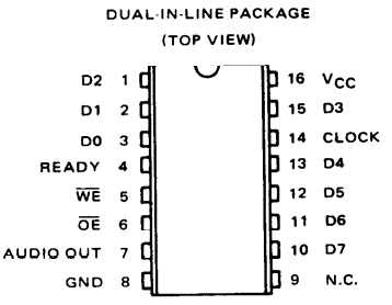
As a programmer, in order to tell the 76489 what to do, you write to a certain address to set the chip’s registers. What this abstracts away is the following hardware procedure:
- Decode the address provided to set the (chip enable) pin on the 76489.
- Figure out if the CPU is reading or writing. We are writing, so set the (write enable) pin on the 76489.
- The CPU puts the “set byte” on the data bus.
- The 76489 sets the READY flag low, so that the CPU will wait for it to finish looking at the value on the data bus.
On the original wiring of the SG-1000, READY is connected directly to the pin of the Z80 CPU. What’s all that READY business? It seems that because writing to the 76489 takes so long, the active-high READY pin is set to false/low in order to put the CPU into active-low while the sound chip is chewing on something.
This way, the game developers don’t have to add extra wait states and guess how long the 76489 will take to ingest a command – the CPU just will block until the sound chip is ready for more.
In other words, it looks something like this:
| Sound chip is doing what? | READY says what? | CPU does what? |
|---|---|---|
| Sitting idle | READY (high) | is high/disabled, so continues running the game as normal |
| Working on something the CPU just said | NOT READY (low) | is now low/enabled, so CPU is held in wait |
Of course, I screwed this logic up and had to pull it up earlier. That pull-up is still present (and required by the 76489 documentation) so that the CPU doesn’t think is always low.
Originally, the 76489 was wired up in the Enri schematics as having the (write) pin from the CPU attached directly to the (write enable) pin on the sound chip, and the decode line connected to the pin on the sound chip. That made a lot of sense to me, so why wasn’t it working?
I was out of ideas, so I swapped the 76489 out for one that I knew was good from a failed Leako revision. Unfortunately, this didn’t seem to change anything, but I did notice/hallucinate some faint garbage noise when I thought sound effects or music were supposed to happen, like when Flicky got caught by a cat.
I became very suspicious of the fact that both the pause and the sound were screwed up, and that those two things just happened to interact in a way that confused me.
Using this PNP transistor on the Enri schematic, controlled the gate for a transistor between , a pullup, and , which was itself pulled up on the other side.
Because I didn’t understand it, the right (read: easy) thing to do was to just cut it out of the circuit. would still get pulled up so the game would run, and the pause button wouldn’t get involved with instruction cycles. Sound would work closer to how the ColecoVision does it. In a very satisfying move, I snipped the 2n3906 out of the board and fired it up.
Glorious sound. Flicky’s little theme song was blaring out of my speakers.
However, now the game would lock up with stuck low, when I moved Flicky and made the screen scroll (if I didn’t move her, I could run the game for several seconds until a cat got her.) It seemed that transistor’s interaction with was significant after all.
A Pause That Antagonizes
The pause button was still sort of finicky. But it did work.
So what was wrong with this little pause circuit, other than making absolutely no sense to me?
On the Mark III/Master System schematics, the “pause” logic is much more obscured. For those later machines, the pause button is just a button with a pullup, hooked to a pin called in a custom chip (VDP or gate array.)
From there, the gate array must synthesize and hand it to the CPU in order to trigger the jump into the “pause the game, please” interrupt. Of course, since the circuit of the internals of the gate array isn’t documented on the service manual (repair technicians usually aren’t building whole new ICs) I have no idea what these machines do to make from .
To make matters worse, is not consumed by the VDP. That means that signal must not be involved in the newer machine’s decision of when to trigger and thus pause.
What about the SC-3000? Well, it doesn’t have a pause button at all. It’s not clear to me why.
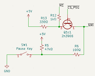
I got really lucky here and found someone else complaining about the same problem on the smspower forums. Google actually didn’t turn this up at first, until I explicitly searched for “Q1c sg-1000.” That’s a little worrying. The original poster, kamillebidan, was willing to come back and answer my questions.
It seemed likely that it was simply a mistake in the schematic, and they even offered an alternative circuit, which I shamelessly stole.
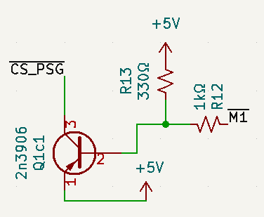
This makes more sense now: when the CPU is busy trying to run an instruction, it will hold the PSG select high, so that the CPU won’t drop into , and hang the CPU forever in a state that it can’t get out of.
Some confirmation from real SG-1000 owners worked out that the pause button was in fact directly connected (or at least, with a pull-up) to the pin.
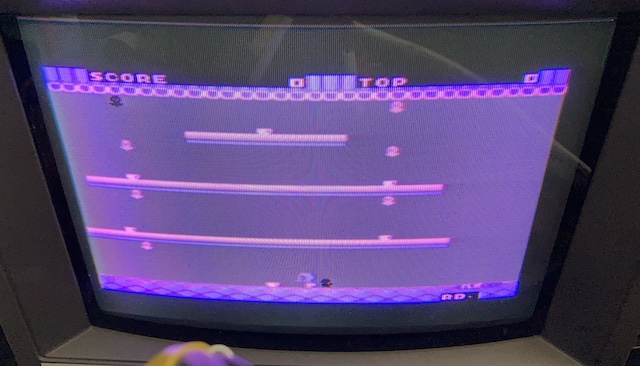
This worked – I could now play a whole round of Flicky. Of course, I died a lot, but I’m pretty sure that’s not the hardware’s fault. I am hugely grateful to kamillebidan and asynchronous from the smspower forums for basically giving me the correct answer.
Sega My Card games inserted into a Card Catcher also work, which is not a surprise, but is nice to see.
My Card Catcher’s PCB seems to be a little thin for the EDAC cartridge connector, thinner than a regular ROM cartridge game, so it needs a little tweaking to get everything to boot properly. Either that, or the internal card connector is dirty - it’s hard to access for cleaning. Here is Chack ‘N’ Pop running, which is the only My Card game that I own.
Next Steps
Now that I have a working SG-1000 clone, it is time to get freaky with it.
Huh, what’s that edge connector sticking out of the end for?
-
You may be curious what Telegames told Americans the second cartridge slot was for. The answer? They didn’t. Ah, the 80s. ↩