Make Your Own ColecoVision At Home (Part 5 - Making More)
Tags: console coleco colecovision leako homemade-hardware homemade-software clone
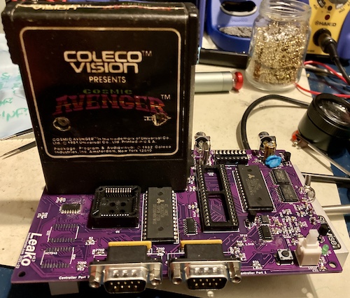
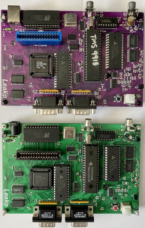
Leako – my ColecoVision clone – has reached a point where it has to become a thing that is actually buildable by other, more normal, people. On top of that, we’ve got chip and part shortages out the wazoo, and a smattering of bugs and reliability issues to knock down. Will revision number seven be the charm?
What’s New?

This revision of the board was mostly to try and improve reliability of the machine. While heavily testing (playing with) my previous-generation board, a lot of things bugged me.
Power Supply
For starters, I didn’t like that Leako version 6 relied on a barrel jack to provide the regulated +5VDC power to run the rest of the system. Not only do you have to worry about the quality of the regulation, and find a compatible adapter, but I also added some (still untested) protection circuitry to avoid reverse-polarity episodes. If there’s one thing I’ve learned from reading console-repair articles, it’s that the average person does not understand DC barrel jack polarity.
I had a couple options, such as designing a polarity-independent input circuit, going up to a 9VDC input and adding a 7805, or finding another way to power it altogether.
In the end, I ended up going with USB, as I had on my Sega SG-1000 clone, the Soggy-1000.
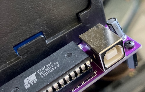
Getting a USB “B” jack is fairly inexpensive, it has okay strain relief, and everyone has a couple USB power adapters lying around. Of course, it’s not a panacea: some USB power adapters are a ripple-fest with terrible regulation, because USB was never really intended to be a universal power supply. Some chargers will push around 5.25V or even higher, which might damage some of the salvaged ICs. I ended up using a nice (but $18) Anker wall-wart to test my system with, and I was fairly happy with the results.
McTwist
There’s a lot of strain issues on the version-six board. For one thing, the force of putting a cartridge into it made the board dip like jumping on a diving board, because nothing is supporting the board in the middle. That twisting will eventually produce bad solder joints, and maybe even shorts or board damage. I put a hole to mount another board standoff near the cartridge to fight this, but I didn’t do it quite right. More on this later.
I also wanted to adjust the controller ports so they didn’t hang as far off the board, and use a port that could be “clipped” into place. While testing all the controllers on the previous iteration of the board, I was getting worried about how much the controller ports were twisting around when plugging and unplugging. Broken solder joints are no fun, and torn pads definitely wouldn’t be.
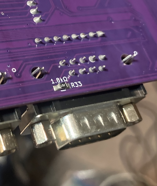
The change in controller port part worked great, and only required minimal re-routing to make room for the changes. Unfortunately, when I was defining the custom footprint for it in KiCad, I forgot to add a ring of copper to solder the pins to. As a result, the springy “strain relief” pins on the controller port are not soldered down, which significantly weakens them. Oops.
Since then, I’ve replaced the entire footprint with one provided by the manufacturer. It didn’t show up on this v7 board, but that’s life.
Shortages
Naturally, the ongoing component shortage nightmare was going to hit me, too. I got off pretty lucky, considering.
I ended up tweaking the system to take a different power-switch FET, and used a Maxim ICL7660 voltage inverter in lieu of the original TI part to generate the -5V.
The most annoying part was waiting for 74LS541s to come back in stock. TI’s 74-logic fabrication was apparently moving to a new process at the time, and they were slowly certifying and reintroducing their chips in order of descending popularity. Apparently the ‘541 isn’t a very popular part because I had to wait over a month for it. More on that in a bit.
Miscellaneous
To make assembly faster, I went through and labelled all the parts on the board with silkscreen. Now, you can tell where passives go just by looking at the value on the board, which makes it a lot easier to stuff the board. Prior to this, I used a printout of the BOM (bill of materials) and crossed it off with a pen as I went. There were some other improvements relating to BOM as well, which I’ll cover later in this article.
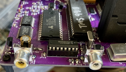
I found out that the manufacturer of the RCA jacks I had been using also made them in various colours. To make sure I plugged video into the video port, and audio into the audio port, I picked up the correct colour for those jacks and specified them in the BOM. It’s the same footprint regardless, but the colour-coding helps make it feel a little bit more professional.
Reliability-wise, I also grounded all the unused inputs for the 74 logic after hearing about this practice from Dave Park in the X68000 PRO power supply rebuild. I think it lowered the current draw, but I can’t really be sure. Either way, doing so is a good idea.
Last, I put a nice little radius on the board’s corners. It didn’t really show up well after fabrication, but the corners do seem less “pokey.”
The BOM Generator Script
KiCad comes with a Python script (“plug-in”) which will generate a bill of materials (BOM) CSV file automatically from your project. I’d had problems using the script before with previous versions of the Leako, so I ended up taking theirs and hacking it up.
The biggest problem I wanted to solve was that Digi-Key’s BOM CSV importer just didn’t understand the file. Most of this was because the Digi-Key importer was very immature up until recently, and would spit my file back out, rather than give me a way to fix it or even hand out a reasonable error message.
Their documentation also didn’t say what the field names it was expecting were. All of my Digi-Key part numbers are tracked using a DigiKey field in their respective KiCad symbols, for instance. I ended up creating a new BOM using their web editor, putting some random garbage in it, and then exporting it to CSV to see what it would produce. Then, I copied those column names into the Python script, and made it re-map the DigiKey field into Part Number.
Digi-Key also lets you enter a little descriptive text next to the parts you buy, and then they print this on the baggie that they put the parts in. To make assembly go faster, I wanted to print the location of each part on the bag. That way, I could reach into the box, grab a bag at random, look at it, and know where that part should go. I ended up mapping the KiCad field References to Digi-Key’s Customer Reference. I didn’t need to do this part, it turns out, because Digi-Key’s web UI had matured enough that it would just let me designate any column as Customer Reference. Still, it’s nice to have.
In the future, I will also add the project name as a configurable prefix, so that I can order multiple projects’ BOMs in one box, without getting confused about whose “U1” this particular bag belongs to.
The final feature I wanted to add to the BOM exporter was footprint splitting. KiCad considers a socketed IC to be just one part: the socket. It only exports one row for that part, so I have ended up doing stuff like buying RAM, but no sockets for that RAM. We’ll talk more about that specific screw-up in a bit.
When I’m buying from Digi-Key, I want to order two parts – the socket, and the part that goes in it. For these cases, I ended up making this field into a semicolon-delimited list1, and then having the plug-in generate separate rows for each token in the list.
It would have been nice to add a configurable (or at least pulled from project information) prefix. This way, if I use this again in the future and order multiple different projects, I don’t have to guess if a given bag’s “U6” designator refers to the Leako, or the Soggy, or what. This will probably get fixed right around the time I have this problem, or shortly after.
At the time of writing, I have since upgraded to KiCad 6, which appears to have a whole new plug-in architecture. This means that I’ll probably have to do all these changes again for future projects. C’est la vie.
Procurement
This version of the project had two aims:
- To build a second Leako;
- To ensure that my BOM (bill of materials) was reproducible, i.e. that I wasn’t missing some parts. My big fear was that I would give someone the BOM, they’d spend some of their hard-earned money to buy it, and they’d end up with not enough parts to build a working system.
As it turns out, my only major BOM error was that I only used the fancy new “splitter” feature on the CPU socket. I should have also specified some DIP sockets for the expensive 62256 SRAM; as it is, they ended up soldered directly to the board. Oops.
Here’s how many parts you get if you order just enough for one (1) Leako, and occasionally click the “cost optimizer” for things like caps:
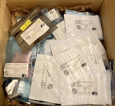
Once all the components were removed, this made a huge amount of plastic waste, which I’m not too excited about. My shop only has so much capability to re-use empty plastic bags…
Additionally, as you might expect from the current semiconductor shortages, the price of the BOM went way, way up. I estimated the previous BOM at around fifty dollars; this one is over eighty bucks, which starts to make this project feel like it’s not much of a cost savings over a garage-sale ColecoVision at all. The PLCC Z80 CPU is particularly expensive, making up $12 of the total BOM price, and has since also famously gone out of production.
This huge increase in build cost is very demotivating, and it will probably affect my designs in the future2. Hopefully, all these cool 5V parts will keep getting made, and the prices will return to normal.
As I mentioned earlier, there was also the shortage of 74LS541s; they shipped separately, almost a month later. This meant that I was sitting for a few weeks with a Leako that I couldn’t control, which had some interesting consequences that I’ll get into later in this article.
Used Parts Accepted Here
That ends the new parts. The Leako still needs three no-longer-produced “vintage” parts from other systems in order to work, and so these must be obtained from salvage:
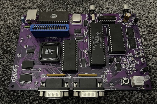
- The Texas Instruments TMS9918 video display processor (VDP;)
- The Texas Instruments SN76489 sound chip;
- A 27c256 (E)EPROM to contain the Coleco BIOS3
While being an idiot, I had broken a leg off of a 27C257 EEPROM awhile ago, and soldered a new pin header leg in its place. This wasn’t reliable enough for regular insertion-and-removal from a socket, so I decided that it would see its permanent home in this system. I wrote four copies of the no-delay BIOS to the EEPROM (using a script that was developed for a future ridiculous project – stay tuned) and shoved it into the socket.
I had also ordered a set of TMS9918 video chips from a trusted seller on AliExpress, but when they arrived they were one chip short, and had all their identifying markings scraped off. The seller/AliExpress refunded me the entire purchase price, but I had a suspicion that they were still TMS9918s. Doing resistance checks and comparing those checks with a “known” TMS9918 confirmed it. I populated the remaining sockets with one of these salvaged TMS9918s and one of my also-dwindling hoard of working SN76489 sound chips.
As 9918s get scarcer, future versions will likely use the Pico9918: while I really like the look and feel of the original part, the Pico9918 shaves the most expensive five chips off the BOM (SRAM, the three latches, and the 9918 itself) and adds RGB output.
Assembly Notes
The “v0.7” board makes a couple of changes, and not all of those changes were for the better.
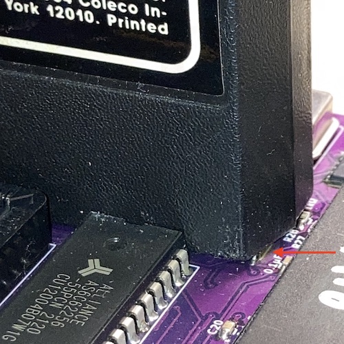
One big trap is that I found out that the 10µF load capacitors for the ICL7660 -5V regulator were placed way too close; it was hard to drag-solder the chip’s legs without hitting them.
Assembly on the 74LS574 VRAM latches still sucks: the pads are too tight so you have to very precisely place the chip to get enough “meat,” and the chip is too tall to hold with tweezers. I made the pads slightly wider on the v0.8, which might make things easier, but I’m not planning on building one anytime soon – at least not without some exciting new features.
I also had moved the series electrolytic capacitor responsible for the composite video output closer to the connector. This, unfortunately, meant that the cap now occupied the same space as the tip of the composite video plug if you had a particularly deep one on your video cable, as I do. Oops.
Assembly overall took me about four hours. I’ve gotten a lot faster this time around than with the last board. Almost all of this performance improvement can be credited to better tools.
Better Tools
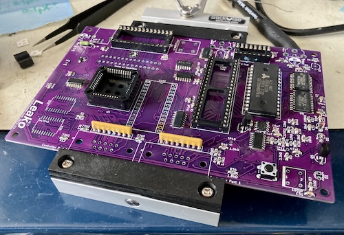
The best investment by far was the StickVise. This is basically a horizonally-aligned clamp that lies flat on your desk and holds the board about a centimeter off the surface. Its clamp is just loose enough that you can slide the board out, flip it over, and slide it back in when you want to look at something on the other side. A genius tool, and 100% worth the money. I should have bought this years ago.
As with the BlueSCSI build from a few years ago, I used blue poster putty to hold in the through-hole components so that they wouldn’t fall out when I turned the board over to solder them down. StickVise now makes this weird springy holder – the PartLift – to push parts up against the board, and I picked up one, but I was afraid of using it for some reason.
Making the “BOM generator” script print the locations of each part on the little Digi-Key baggies was also a huge time saver, as was the labeling on the board. This way, I could pull a bag out of the box at random, and immediately know how many parts needed to be used and where they went. No need to look at a printed-out BOM.
The new-to-me Kester 63/37 solder helped a lot with drag-soldering of SMD ICs. It seemed to flow much more like how I want, without cold solder globs building up on the tip. There were still bridges and underfills, but it felt more like it was my fault when they happened.
Uncontrolled Test
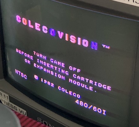
I hooked the Leako board up to my Anker USB power brick, with a USB voltmeter/ammeter in between4. Initial power-on showed that it was pulling about 0.29A at 5.08V sitting on the BIOS screen, which is more or less what the original, DC-plug, Leako pulled. Good indicator, so let’s strap it up onto a TV and check the video.
I did find one serious, but survivable, boo-boo during assembly. With a mounting screw installed into the new strain-relief position near the cartridge, it would add a little bit of height from the head of the screw sticking out. The bottom of the cartridge case would interfere with that head, and the cartridge PCB would not make full-depth contact with the connector as a result. This renders the new strain-relief hole useless, unless I somehow find some very low-profile screws.
I’ve since moved the support mount’s hole to the side of the cartridge slot, where it should only be threatened by an empty space under the cartridge shell.
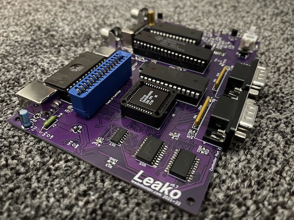
The cartridge shell also now interfered with the 74LS04 and 74LS74 at U11 and U20, respectively. This was a big surprise, and a huge disappointment to come right at the end of the assembly process.
Before, the cartridge would just barely clear the tops of those packages, whereas now it sits a little cockeyed and would sometimes keep carts from booting. I wasn’t sure why this didn’t happen before, but as soon as I compared the two boards, I realized I had made a mix-up in the BOM between revisions and ended up using a different cartridge slot.
That new, blue Sullins slot places the cartridge just a teensy-tiny bit closer to the board than the old black TE AMP cartridge slot did. The datasheets said the housings were both 15.49mm tall above the PCB, but the TE AMP datasheet says the insertion depth is 0.05mm shallower (7.54 vs. 7.49), which can’t possibly make that big of a difference. Without an answer to my mystery, I shrugged and changed the BOM to use the TE AMP part, and moved a chip a little further away from its landing zone just in case.
The crooked approach didn’t interfere with cartridge reading, but in the future versions, I will also flip these offending ICs to the underside in order to make it much easier to put the cart in.
Uncontrolled Test
However, all was seemingly not well with the assembly. Since the ‘541s were missing, the console thought that all of the joystick buttons were being pushed at once.
More concerning is that Cosmic Avenger came up fine with tile graphics and “smooth” scrolling, but the player ship looked corrupt - just a couple of coloured squares.
I had assumed that, like the original bring-up of the Leako, I had simply not soldered the surface-mount ‘574s which feed the video RAM properly. As a result, wherever the game was sticking the sprite tiles into video RAM was not being read or written properly. Although I had paid special attention to the ‘574s during pre-flight inspection, I was also really tired – a recipe for failure.
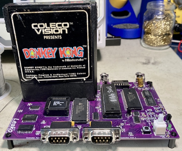
I broke out the jewelry loupe and a very strong light to take another look. Everything looked fine there, so I tried another game. Donkey Kong worked 100% fine. In fact, really well. Buoyed by the missing controller, Mario ran all the way to the right of the screen, and hid there in the corner for several seconds until a particularly determined barrel finally got him.
Controlled Test
Eventually, some 74LS541s rattled loose from the distribution network. These had a then-new 2022 date code on them, so they must have been fresh out of the oven, after TI’s aforementioned change in fab process for their 74s.
Unfortunately, when I fired up the system, I found that it blew right past the BIOS screen5, and then got stuck on the skill select screen. No amount of pushing buttons on either my homemade joystick or a known-good Super Action Controller would make the game run.
I thought hard about what I had changed on the controls between revisions of the Leako. Pretty much everything was the same, except for the -5V generation. It had changed from the out-of-stock TI charge pump chip to a ICL7660.
I should have checked that when I did my first fire-up even before the ‘541s arrived, but no time like the present. With the red probe of the multimeter on the -5V test point, and the black probe on the ground test point, I was observing +1.6V. That’s quite a lot more than -5V… what happened?
After closely inspecting the tight spot that I had to solder the ICL7660 in, I wasn’t satisfied with the soldering job. I desoldered the 10µF that was too close to the pins, then reflowed the pins… like I should have in the first place. Always check your work while it’s easy! It looks like pins 2 and 3 (oscillator cap positive and ground, respectively) were not well-attached. Now, I was getting a reliable -5V (or at least, -4.8V.)
Getting the -5V generation to work properly, sadly, did not measurably improve the system’s performance. The same “autofire” phenomenon happened, except when testing it this time I noticed that I could pull right on the joystick to bypass the skill select menu. So it was treating some “fire” inputs as “number pad” inputs.
I cut the ICL7660 out of the circuit entirely and pulled the joystick down to GND instead of -5V. I’d never felt great about this “super pull-down,” and now was the chance to see if it worked okay without it. The verdict: sort of. My custom-made joystick worked great, but the Super Action Controller’s more complicated maze of diodes just didn’t reliably respond to joystick inputs.
On top of that, even though I had a working joystick of sorts, pulling down and to the right was treated as the equivalent of pushing the “*” button on the system, pausing the game. And the song it plays when paused on Frenzy is really freaky; it’s squelchy and hummy enough to make you think you’ve broken your system. Once I figured out that the game was pausing instead of just breaking, a lot of things fell into place. Namely, I could kill a full room of robots in Frenzy as long as I didn’t touch the diagonals. Nice.
So, it seemed to me that the mode-select logic wasn’t working. Why not? It turns out that U23, the 74LS00 that makes up both halves of the “flip-flop” that handles mode-select latching, was not well-soldered on pin 6. It looked fine from a casual glance, but at a certain angle and with strong lighting you could see some exposed pad. After touching that up, and also the pads around it for good measure, I now had the ability to play Frenzy with the correct buttons!
Just like with the first board’s weird graphics, the fault was my poor SOIC-soldering skills. I’ll definitely have to spend more time checking my joints from now on, and take more time around ground pads that need a little extra heat.
Frenzy and Zaxxon are a lot of fun with the Amazon-parts joystick controller. The leaf-switched joystick lets you place the movement more precisely, and it makes these games just that little bit closer to arcade-perfect. I would strongly recommend building something like this to any ColecoVision owner.
Just to confirm that it wasn’t the -5V’s fault, I went and re-implemented my bodge to pull the controller to ground instead of -5V. The Super Action Controller also worked with the pull-down tied to ground instead of -5V, although it seemed a little glitchy moving up or right, which may just be the nature of that controller. More testing is necessary in this configuration.
A Third Leako
The Cambridge Centre for Computing History was doing an anniversary exhibit, and wanted to see homebrew examples of systems released in 1982. I sent a bare board of the Leako (along with a bare board of the Soggy, for next year) to blog superfriend Pete Golding, who then actually bought all the BOM, and assembled one of his own clones.
Unlike me, he didn’t drag-solder, and seems to have ended up with better results. There were some bad joints on the ‘574s that needed to be cleaned up before the video would display properly, and one of his TVs got very angry at the signal and refused to display colour at all. I suspect the 33pF load caps on the clock crystal are simply the wrong value, so I will add an adjustment pot in future versions.
Thanks for being a guinea pig, Pete!
A Fourth Leako
Blog friend Famiclone also tried to assemble one at this point, but ended up with one that didn’t seem to be able to boot games or the internal BIOS. Long-distance debugging hasn’t worked so far, so I am regretfully going to get them to ship it back to me and see if I can figure out what’s gone wrong.
A Fifth Leako
Blog friend Cheshire has also built one! He reports that quadrature controllers are still not working quite right, and he has a theory that I used the wrong logic family. We’ll work together to figure out what the problem is!
Conclusion
This phase of the project was full of ups and downs.
There’s obvious progress: the system still works. More Leakos got built, and more of them successfully ran games. That means the total number of ColecoVision systems in the world increased. One got built and run across the ocean, for museum visitors to see! It’s got a reproducible BOM, which you can buy parts for! I reused part of the design to make a Sega SG-1000 clone, and then brought those fixes back to the parent board!
On the downside, a lot of the new stuff I tried out didn’t work. I am still rushing through the soldering, which makes for an unreliable system that’s challenging to debug. The cartridge-interference issue practically forces a new revision of the board, which means more assembly time and expense, just for the sake of a chip being moved a little further over. Shortages continue to dog this project, as do flaky original controllers.
I was expecting a triumph and got kind of a weak “good enough.” That’s why this blog entry is coming out several years after the board has been assembled and tested – the whole thing bummed me out, even though I should be really happy with how far it’s come.
Don’t worry, though. This isn’t the last you’ve heard of the Leako project, and I’ve already made some changes to my technique and the board’s design to promote a more reliable outcome next time.
-
For instance, the PLCC socket and the PLCC Z80 that goes in it is entered as
2057-PLCC-44-AT-ND; 269-3899-ND, respectively. ↩ -
For instance, the Soggy-1000 revision that was made after this has already gone to a salvaged $1 DIP Sharp LH0080A for its CPU rather than these expensive and now no-longer-made Z80s. ↩
-
27c256-compatible EPROMs might actually still be in new production somewhere, but you can buy a vacuum-packed brick of old ones from AliExpress for about fifty cents apiece. Waste not, want not… ↩
-
This inline USB voltmeter/ammeter really freaked out my Rigol digital oscilloscope whenever I tried to take readings with it mounted – the Rigol would read ridiculous voltages on logic pins. I only needed that ammeter for the initial bringup, but I kept it connected because it looked cool. ↩
-
For this specific unit, a “No-Delay” BIOS was flashed onto the BIOS EEPROM, which lets you skip the otherwise unskippable 12-second countdown on the “ColecoVision Presents…” screen and get right into the game. It makes testing a lot faster. ↩